Quick Start Guide PRELIMINARY EDITION 28--MAR--02 164.
ITRF24501 Reader Quick Start Guide Packing List WARNING: This is a Class A product. In a domestic environment this product may cause radio interference in which case the user may be required to take adequate measures.
ITRF24501 Reader Quick Start Guide Host Communication Host communication comes through the 9-pin female D-sub connector. Both RS-232 and RS-422 standards are supported as ordered from the factory or service center.
ITRF24501 Reader Quick Start Guide Power Requirements Power comes in from 8 to 10 volts DC. The Fixed Reader uses less than 2 amps. Intermec supplies 9 volts DC at 2.4 amps from Intermec power supply, #351-066-001. User I/O A general purpose I/O (Input/Output) connector provides signal lines in and out of the reader allowing monitoring and/or control of external devices or functions. The connector for this is a 13-pin female circular DIN.
ITRF24501 Reader Quick Start Guide climb higher as the sink current increases. There is no protection on this. You need to ensure that their load won’t require the reader to sink more than 50 mA. Input signals should be 0 to +1.5 volt for a low input and +3.5 to +5 volts for a high input. Each input has a 1.1 kohm resistor in series with clamping diodes, but only about 1PA is used until the input exceeds the 0 to +5 volt input range. There is also a weak (100 kohm) pull--up to +5 volt on each input.
ITRF24501 Reader Quick Start Guide Connecting and Getting Started WARNING: FCC regulations limit exposure to radiofrequency (RF) radiation. To comply with these regulations, operators of this device must maintain a distance of at least 20 cm. (8 inches) from the cover on the antenna assembly (The cover on the antenna is the dome shaped surface). While the device is on, the operator’s body and parts of the body such as eyes, hands, or head, must be 20 cm.
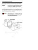
ITRF24501 Reader Quick Start Guide Antenna Installation Ensure that you read the above warning before installing the antennas and using your Reader product. Reader to antenna cable Mounting bracket Back view Front view 1. Review the locations where the Reader products need integrated. Ensure that you have careful considered the safe distances for product placement for workers and any other personnel that may get in the RF path. 2.
ITRF24501 Reader Quick Start Guide The following illustration is an example of a typical Reader installation. EXAMPLE: Two Product Line Conveyers, showing two antennas on each line. Two antennas in a crossing pattern provide angular diversity to improve read capability when tag orientation is unknown. The frames for these stations are PVC tubing with RF reflective Mylar liner X2.
ITRF24501 Reader Quick Start Guide Connecting the Antenna to the Reader 1. Connect the antenna cable to a port. 2. Connect an SMA reverse--sex SMA terminator (Intermec p/n 345-004-001) to any port that does not have an antenna attached. " NOTE: Each port must have either an antenna or a terminator connected. Antenna ports 1 3 2 4 SMA terminator Back panel Antenna cable 3. Connect the Reader to a power source using power supply p/n 351-066-001 and country dependent AC power cord. 4.
ITRF24501 Reader Quick Start Guide 5. Review the front panel LEDs to become familiar with the status indications you will receive from your Reader. LEDs (left to right) Auxiliary I/O connector RS-232 or RS-422 port Power supply jack I (ON) O (OFF) switch LED Meaning LED 0 Reader has power is initialized and ready. LED 1 Reader is communicating with the host, it flashes as data transfer occurs. Reader RF is ON and searching for TAGs.
ITRF24501 Reader Quick Start Guide Troubleshooting Table 1-4 Troubleshooting Problem Solution Doesn’t recognize tag 1. Check to ensure antenna is connected to jack on Reader. 2. Ensure Reader is connected to your computer. 3. Ensure computer is plugged into ac outlet and computer is turned on. 4. Ensure tag is within range of antenna. 5. Access the Intermec web site http://www.intermec.com or http://NorBBS.Norand.com to download and run the diagnostic test utility PENNRFID.EXE. 6.
ITRF24501 Reader Quick Start Guide Performance Specifications Dependent upon operating conditions and demands expected. If used in a normal office environment with good read conditions, you could expect to read up to 30 tags per second. Tags located too far away or in poor locations, with respect to interfering objects, provides poor results.
ITRF24501 Reader Quick Start Guide Table 1-5 (Continued) ITRF24501 Reader Specification Criteria Range Vibration 1.0 GRMS. 10 to 500 Hz in three axis Channel switching 30 uS (TX on a channel, to TX on any other channel) Frequency stability --50 to +50 PPM Transmitter power output 900 mW(typical) 1000 (max.) mW @ connector. Assume 1 dB of antenna and cable loss across total passband. Safety Approvals USA: UL Listed, C22.2 No.
ITRF24501 Reader Quick Start Guide Corporate Headquarters 6001 36th Avenue West Everett, Washington 98203 tel 425.348.2600 fax 425.355.9551 www.intermec.