
User's Manual Part 3
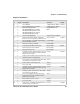
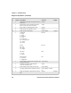
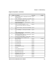
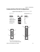
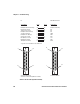
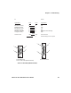
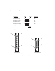
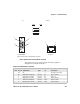
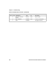
Table Of Contents
- Checking the Power Source
- Aligning the Printer Mechanism
- Troubleshooting System Components
- Understanding Diagnostic Information
- Communications Pin-Out Configurations
- Specifications
- Printer Dimensions
- Media Specifications
- Understanding the Fanfold Paper Page Layout

Chapter 6 — Troubleshooting
6822 Series 80-Column Printer User’s Manual 123
Data Communications Cable (P/N 226-270-XXX)
The printer has a 25-pin connector with the following pinout
designations and signal mnemonics:
PC
Printer
RJ-11 Jack
Pin #
7
5
3
2
8
Pin #
6
5
3
2
1
9-Pin DSUB Male
Data Communications Cable (P/N 226-270-XXX)
5
1
9
6
1
6
Printer Communications Connector
15-Pin
D–Sub
25–Pin
D–Sub
Signal Name Type I/O Description
1 NC NC – – – – – – NC (No Connection)
2 20 DSR (Data Set Ready) RS-232 IN Printer’s DSR
3 4 CTS (Clear To Send) RS-232 IN Wake up
4 2 RXD (Receive Data) RS-232 IN Printer’s RxD
5 3 TXD (Transmit Data) RS-232 OUT Printer’s TxD
6 5 RTS (Ready To Send) RS-232 OUT Printer’s RTS