
User's Manual Part 3
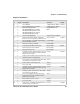
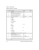
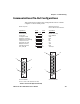
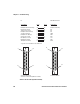
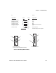
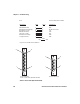
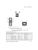
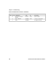
Table Of Contents
- Checking the Power Source
- Aligning the Printer Mechanism
- Troubleshooting System Components
- Understanding Diagnostic Information
- Communications Pin-Out Configurations
- Specifications
- Printer Dimensions
- Media Specifications
- Understanding the Fanfold Paper Page Layout

Chapter 6 — Troubleshooting
6822 Series 80-Column Printer User’s Manual 119
Communications Pin-Out Configurations
This section shows common cable configurations between a mobile
computer or a dock and the printer.
15-Pin to 25-Pin Cable (P/N 216-605-1XX)
Mobile Computer
Signal Name
Chassis Ground
Charge Input
SG (Signal Ground)
DSR (Data Set Ready)
DTR (Data Terminal Ready)
CTS (Clear To Send)
RTS (Ready To Send)
RXD (Receive Data)
TXD (Transmit Data)
Dock_A/B_SW
Wall Mount Printer or
Remote Mount Terminal Holder
15-Pin DSUB Male
15-Pin to 25-Pin Cable (P/N 216-605-1XX)
25-Pin DSUB Male
Signal Name
NC (No Connection)
HHC_CHARGE
GND
DTR
NC
RTS
CTS
TXD
RXD
Term A/B
Pin #
shell
8
9
7
2
6
3
5
4
NC
Pin #
1
9
7
6
20
5
4
3
2
12
shield
8
1
15
9
13
1
25
14