
User's Manual Part 3
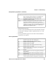
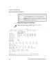
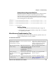
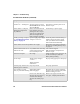
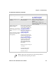
Table Of Contents
- Checking the Power Source
- Aligning the Printer Mechanism
- Troubleshooting System Components
- Understanding Diagnostic Information
- Communications Pin-Out Configurations
- Specifications
- Printer Dimensions
- Media Specifications
- Understanding the Fanfold Paper Page Layout

Chapter 6 — Troubleshooting
6822 Series 80-Column Printer User’s Manual 109
• Head Dot Pattern (line 37)
Is used to verify the individual dot wires. There should be nine dots.
If some dots are missing, it could be a printhead failure or a circuit
board failure.
• Error Log information appears on lines 38-43. This information is
cleared after every self-test.
Step The acceleration step at the jam. 0 means no steps were
taken, 15 means all steps were taken. 1-14 indicates the
printer jammed during acceleration or deceleration.
Temp The ambient temperature at the last head jam. The
temperature is listed in Celsius.
Position Position of carriage at the time of the jam in 1/720 in = 12 *
step position. Divide the number by 12 to get the step
position. There are 512 steps across the page. If it is jammed
at position 0, check the printer mechanism alignment. If it is
jamming in the middle, it is more likely a dirty ribbon or
obstruction in the printhead’s path.
Head Jam History Information (continued)
Heading Description
Error Log Information
Heading Description
PE Number of paper jams while feeding paper
HJ Number of head jams while printhead is moving
12Vu Number of 12 V under-voltage
12Vo Number of 12 V over-voltage
24Vu Number of 24 V under-voltage (head/motor voltage)
24Vo Number of 24 V over-voltage
Home Number of home detect errors (typically caused by paper
scraps or circuit failures)
Temp Unused
OverC Number of head over-current errors (typically caused by a
bad printhead)
HeadS Number of head driver short errors (typically caused by
circuit failures)
Fault Number of paper feed motor over current errors (excess
current in paper feed motor could indicate circuit failure)