
User's Manual Part 2
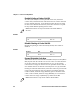
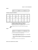
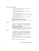
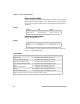
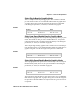
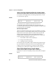
Table Of Contents
- Connecting to the Printer
- Understanding the Font Modules
- Using the Windows 95 or Windows 98 Printer Configuration Utility
- Using the Windows 2000 or Windows XP Printer Configuration Utility
- Understanding Control Code Definitions
- Using Printer Control Codes
- Backspace
- Beeper
- Cancel Line
- Carriage Return
- Delete
- Form Feed
- Select Half-Speed Printing
- Cancel Half-Speed Printing
- Set Inactivity Time for Sleep Mode
- Line Feed
- Perform Master Reset
- Set Print Position (absolute)
- Set Print Position (relative)
- Page Formatting Functions
- Character Style and Text Mode Functions
- Defining Intercharacter Space
- Tabs and Tab Setting Functions
- Using Character Sets and User-Defined Functions
- Single-Byte Character Sets
- Double-Byte Character Sets
- Multi-Byte Character Sets
- Select National Character Set
- Hebrew Character Fonts
- User Defined Characters
- Copy ROM to RAM
- Define User-Defined Characters
- Select User-Defined Character Set
- Select Default Character Set
- Enable Printing of Codes 128-159
- Disable Printing of Codes 128-159
- Expand Printable Code Area
- Enable Printing of Character Graphics
- Disable Printing of Character Graphics
- Printing Character Graphics
- Graphics Functions

Chapter 5 — Control Code Definitions
94 6822 Series 80-Column Printer User’s Manual
Select Low-Speed Quadruple Density Graphics Mode
With this 8-pin graphics mode, the number of dots per inch has gone up
to 4x what it was in single density. Calculating the parameters, n1 and
n2, is described on page 94.
The resolution is now 240 dots per inch. Each 8-in line can
accommodate 1920 columns of graphic dots. A graphic string that
exceeds the length of the print line is discarded. Make sure adjacent dots
in a given dot row are not printed.
Nine-Pin Graphics Modes
These 9-pin graphics functions also require two parameters, n1 and n2.
However, they are calculated slightly different than in the 8-pin graphics
modes. Since two data bytes represent each dot column to print, first
divide the total length of the graphic string (following the Select ...
Graphics Mode command) by two. These parameters are calculated as
follows (assuming a temporary variable n):
• n = total number of dots needed, divided by 2
• n2 = integer of (n divided by 256)
• n1 = remainder of the n2 calculation
First, divide n (the total number of dots needed for the graphics string)
by 2, then divide the result by 256. Then n2 is the quotient (the whole
number) and n1 is the remainder. If you require less than 256 dots
(columns), then n1 indicates the number of dots and n2 is set to zero.
Select 9-Pin Single Density Graphics Mode
Enables Single Density 9-pin Graphics mode. Calculating the
parameters, n1 and n2, is described previously under Nine-Pin Graphics
Modes.
Format
Decimal Hex ASCII
27 90 n1 n2 1B 5A n1 n2 ESC “Z” n1 n2
Format
Decimal Hex ASCII
27 94 0 n1 n2 1B 5E 00 n1 n2 ESC “^” (0) n1 n2