
User's Manual


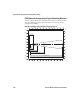


Table Of Contents
- Chapter 6 - Configure the Computer
- How to Configure the Computer
- Use Intermec Settings on the Computer
- Use Intermec Settings Remotely with SmartSystems
- About Network Communications
- About Wireless Security
- Chapter 7 - Manage the Computer
- Chapter 8 - Troubleshoot and Maintain the Computer
- Appendix A - Specifications and Default Settings
- Physical and Environmental Specifications
- CN70 Physical Dimensions
- CN70e Physical Dimensions
- CK70 Physical Dimensions
- CK71 Physical Dimensions
- Environmental Specifications
- Power and Electrical Specifications
- 70 Series Non-Incendive Computer Specifications
- Operating System
- Hardware
- Back Accessory Interface Pin-outs
- Touch Screen Specifications
- Standard Communications
- Wireless LAN
- Regulatory Approvals
- Bar Code Symbologies
- Imager Reading Distances
- EA30 Typical Reading Distances - Extended Reading Range
- EA30 Area Imager Minimum Reading Distances
- EA30 Area Imager Typical Reading Distances
- EV12 Linear Imager Minimum Reading Distances
- EV12 LInear Imager Typical Reading Distances
- EX25 Near-Far Range Imager Minimum Reading Distance
- EX25 Near-Far Range Imager Typical Reading Distance
- Default Configuration
- Physical and Environmental Specifications
- Appendix B - Keypads and Keystrokes
- Appendix C - ScanNGo Wi-Fi Configuration Bar Codes
- Index

Appendix A — Specifications and Default Settings
142 70 Series Mobile Computer User Manual
EX25 2D Symbologies Typical Reading Distances With 0.24 cm (0.09
in) Setback
** Minimum distance depends on bar code width and scan angle.
Default Configuration
The following tables list the default values of the configuration
settings supported on the mobile computer. If you restore the mobile
computer to factory default settings, the mobile computer uses these
values.
The settings are grouped by function and reflect the organization of
Intermec Settings. Not all of the configuration settings are listed in
this appendix. For detailed information on most of the settings, see the
Intermec Settings Command Reference Manual.
Data Collection Settings
Use data collection settings to configure the imager and to configure
the bar codes that you want the imager to be able to read.
Data Collection Settings
Symbology Density Minimum Distance Maximum Distance
DataMatrix 0.25 mm (10 mils)
0.76 mm (30 mils)
1.4 mm (55 mils)
2.5 mm (100 mils)
7.5 mm (300 mils)
15 cm (5.91 in)
25 cm (9.84 in)
**
**
20 cm (7.87 in)
90 cm (35.43 in)
310 cm (122.05 in)
450 cm (177.17 in)
1100 cm (433.07 in)
1524 cm (600 in)
Data Collection Setting Default Value
Enable Scanner/Camera Port On
BT-Configure On Connect Overwrite with computer
settings
Enable Magstripe Reader Disable