
Specification


www.intermatic.com
Energy Controls
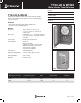
Diagrams
Specification
The time switch shall be a 24-Hour dial type, capable of permitting up to 12 ON/OFF operations each day. The time
switch shall provide a minimum ON/OFF time of 1 hour. The time switch to be powered by 208-277 VAC, 60 Hz power
supply. The time switch motor shall be a synchronous motor, which shall be designed to withstand a minimum of 6000
Volt transients. The time switch motor shall be connected to the supply terminals with ring-type connectors and shall not
require more than 3 Watts to operate time switch. The time switch mechanism shall be a snap-in design to provide ease
of mechanism removal from the enclosure. The time switch enclosure shall be a Type 1 steel lockable enclosure. The
time switch enclosure shall provide a minimum of 31 cubic inches of wiring space and shall provide a non-removable
cover, which shall swing open a full 180 degrees. The time switch shall provide clear terminal identication on a
see-through non-curling terminal insulator. A visual indicator shall be provided in the time switch for inspecting clock
motor operation. The time switch contact blades shall be a one piece design with welded silver alloy contacts and shall
be designed to provide wiping action on contacts during operation to ensure reliable load switching. Terminal
connections shall be made using teeter-type terminal screws to provide secure connections for wire sizes up to #8 AWG.
Switch conguration shall be DPST, with a switch rating each pole:
• 40 Amp Resistive, 120-277 VAC
• 40 Amp Tungsten, Inductive or 1000 VA Pilot Duty, 120-277 VAC
• 2 HP (24 FLA), 120 VAC
• 5 HP (28 FLA), 240 VAC, Single Phase
The time switch shall be Agency Listed under Clock Operated Switches and shall be Intermatic model _______________
(T104-20)(WH40).
7 ¾"
3"
5"
[12.70 cm]
[7.62 cm]
[19.69 cm]
Type 1 Enclosure
T104-20 & WH40