
User's Manual Part 2


Four: Programming the Three-Circult Clock Mechanism 29
Providing a brighter solution.™
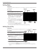
Mode 4 — (Pump High, Pump Low, Cleaner Pump)
Circuit one and two are dedicated single pole
outputs for a two-speed pump load. Circuits one and
two will never be ON at the same time, consistent
with a two-speed pump application. Circuit three
is also a dedicated single pole output for a pressure
side cleaner pump. Circuit three will never come
on unless circuit one is on for at least one minute,
consistent with a pressure side cleaner pump.
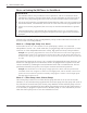
Mode 5 — (Pump, Pump, Aux3)
Circuit one and two are now coupled together
making up one circuit capable of switching the
power source to one pump. The On/Off button for
circuit one now controls both circuit one and two
simultaneously. The On/Off button for circuit two is
disabled. Circuit three remains a single pole circuit
for a generic load, and is independent of circuits one
and two..
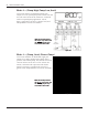
Figure 4-6Figure 4-6
NOTE: This drawing illustrates
that only one leg is broken, with
the other leg going directly to
load, whether 120V or 240V.
NOTE: This drawing illustrates
that only one leg is broken, with
the other leg going directly to
load, whether 120V or 240V.
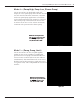
Figure 4-7Figure 4-7
NOTE: This drawing illustrates
that only one leg is broken, with
the other leg going directly to
load, whether 120V or 240V.
NOTE: This drawing illustrates
that only one leg is broken, with
the other leg going directly to
load, whether 120V or 240V.