
User's Manual Part 2


Five: Programming the Valve/Pump Switch Mechanism 35
Providing a brighter solution.™
Section 5:
Programming the Valve/Pump Switch
Mechanism
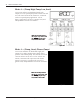
Overview of the Valve/Pump Switch Control Panel
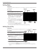
Front View
ACTUATOR CONNECTION —
The Pump/Valve Switch
mechanism supports up to
three 24V valve actuators.
HEATER THERMOSTAT CONNECTOR — supports the three
wires from the heaters thermostat. The wires should be
marked Pool, Common, and Spa. The mechanism will
switch the thermostat when the actuators change.
WIRED OR WIRELESS
CONNECTOR will support
either the wired spa side
remote or the panel-mounted
wireless transceiver.
JUMPER BLOCK
CONFIGURATION — used
when a simple single-pole
single through switch
is going to be used in
conjunction with the Sensor
Line to control the Pool to
Spa Mech. This is the most
inexpensive way to achieve
total pool/spa automation.
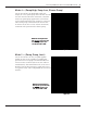
SENSOR LINE — allows the
mechanism to be controlled by
a single pole sing throw switch
(i.e. toggle switch, relay, wall
switch, etc.). See page xxx for
details.
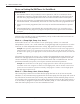
SERVICE BUTTONS —
allow you to operate the
mechanism at the panel.
POOL/SPA
THERMOSTAT SWITCH
— allows you to switch
between the pool and
spa thermostat or just
the spa only. In the spa
only mode, the pool
thermostat is disabled.
DUAL-VOLTAGE TRANSFORMER
— is capable of being powered
with either 120V or 240V.
CIRCUITS 1 & 2 — The pool to spa mechanism
supports up to two auxiliary 3HP circuit loads. You
can have different source voltages for each circuit,
depending on your equipment requirements.