
User's Manual Part 1


22 I-Wave Installation Guide
Copyright © 2006 Intermatic, Inc.
Heater Fireman Switch Connection
The I-Wave Control System is capable of controlling most heaters or heat pumps, using
thermostatic circuitry of 24 VAC or less, in the market today. Locate your heater in the following
pages and follow the instructions for proper installation with your I-Wave Control Center.
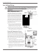
Connection to the Three-Circuit Clock
Connect the Heater Fireman switch to the Intermatic Fireman
Switch wires (tagged), located in the low-voltage raceway of the
Intermatic panel. (See Figure 3-14.)
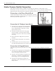
Connection for Teledyne Laars Heater
Connect two #14 gauge wires, designed for
use in hot environments, to the two black
wires, marked heater connection, on the
panel mount receiver.
Connect the other ends of the #14 gauge
wires from Step 1 to the Fireman’s Switch
terminal bar in place of the factory installed
wire loop.
Do not disconnect high limit or pressure
switches.
Turn the heater thermostat(s) to maximum
setting.
Turn the heater switch to the ON position.
For dual thermostat heaters turn switch to Spa position.
Connection for Raypak Heaters
The following connection procedure is for the two wire-one function conguration Raypak
heater.
Connect two #14 gauge wires, designed for
use in hot environments, to the two black
wires on the panel mount receiver.
Connect one end of either #14 gauge wires
from Step 1 to both the orange/black and
black/orange wires on the Raypak heater.
Connect the remaining #14 gauge wire
from Step 1 to the yellow/black wire on the
Raypak heater.
1.
2.
3.
4.
5.
1.
2.
3.
Fireman
Switch
Wires
(Blk/Wht)
Fireman
Switch
Wires
(Blk/Wht)
Figure 3-14Figure 3-14
Figure 3-15Figure 3-15
Figure 3-16Figure 3-16