
User's Manual Part 1


20 I-Wave Installation Guide
Copyright © 2006 Intermatic, Inc.
Low-Voltage Wiring
CAUTION: Your I-Wave Control Center is equipped with a Low Voltage Raceway.
You must use this raceway for all low voltage wiring, including the 12 Volt wires
from the transformer. You cannot mix high and low voltages in the high voltage
compartment.
Water Temperature Sensor
The I-Wave Control System comes equipped
with a Water Temperature Sensor. This sensor is
needed to monitor and maintain both the pool
and spa water temperature depending on the
position of the diverter valves. It needs to be
installed in order for the thermostat control to
work. Power needs to be disconnected when
connecting the temp sensor. Only an Intermatic
Sensor will work with this controller. Follow
the directions below to install and mount your
water temperature sensor. Refer to page 43 For
programming instructions.
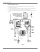
Drill a 3/8” hole in the pipe between the
lter pump and lter and install the Water
Temperature Sensor with hose clamp (not
provided). Ensure the O-ring is in place.
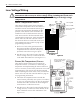
Run the wire to the Control Center, through
the low voltage raceway. Connect both wires
to the Panel Mount Receiver. (See Figure 3-11.)
Freeze (Air Temperature) Sensor
The I-Wave Control System uses an optional Air
Temperature Sensor (178PA28A) for measuring air
temperature and implementing the Freeze Protection
Circuit—necessary for the freeze protection circuit and
programming to work. Power must be disconnected
when connecting the freeze sensor. Only an Intermatic
Sensor will work with this controller. Refer to page 34
for programming information.
Install the Air Temperature Sensor outside the
Control Center, preferably onto a piece of conduit at
or near your equipment pad. Use the clip provided
with the sensor. Do not install in direct sunlight or
around motors or other heat sources.
Run the wire to the Control Center through the low
voltage raceway. Connect Air Sensor directly to the
back of the three-circuit clock mechanism. (See
Figure 3-12.)
1.
2.
1.
2.
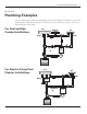
Fireman’s Switch Wires
(Brown/Brown)
Water Temp Wires
(Black/White)
Make
connection
with
connectors
provided
Cable to P1353ME
Cable to P4232ME
Wires from
Water Temp Sensor
(Black/White)
(178PE4)
Fireman’s Switch Wires
(Brown/Brown)
Water Temp Wires
(Black/White)
Make
connection
with
connectors
provided
Cable to P1353ME
Cable to P4232ME
Wires from
Water Temp Sensor
(Black/White)
(178PE4)
Figure 3-11Figure 3-11
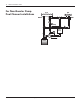
Remove clock and connect
Freeze (Air Temp) Sensor
(178PA28A) here
Freeze (Air
Temp) Sensor
(178PA28A)
Remove clock and connect
Freeze (Air Temp) Sensor
(178PA28A) here
Freeze (Air
Temp) Sensor
(178PA28A)
Figure 3-12Figure 3-12