
Installation Manual User Manual

EN 16 Installation Manual
PC requirements
Intel-based PC 1 GHz or faster
Memory I GB RAM
Operating system Windows® XP, Vista or Windows 7
CGI Direct X 9.0 or later
Browser Microsoft Internet Explorer 6.0 or later
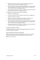
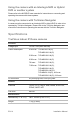
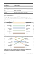
Pin definitions
There are eight wires on a standard UTP/STP cable and each wire is color-
coded. The following shows the pin allocation and color of straight and crossover
cable connection:
Figure 8: Straight-through cable
1 White/Orange
White/Orange 1
2 Orange Orange 2
3 White-Green White-Green 3
4 Blue Blue 4
5 White/Blue White/Blue 5
6 Green Green 6
7 White/Brown White/Brown 7
8 Brown Brown 8
Figure 9: Cross-over cable
1 White/Orange White/Orange 1
2 Orange Orange 2
3 White-Green White-Green 3
4 Blue Blue 4
5 White/Blue White/Blue 5
6 Green Green 6
7 White/Brown White/Brown 7
8 Brown Brown 8
Please make sure your connected cables have the same pin assignment and
color as above before deploying the cables in your network.