TruVision Indoor IP Dome Installation Manual P/N 1072625A-EN • REV 1.
Copyright © 2013 UTC Fire & Security Americas Corporation, Inc. Interlogix is part of UTC Climate Controls & Security, a unit of United Technologies Corporation. All rights reserved. Trademarks and patents Manufacturer The Product Name and logo are trademarks of United Technologies. Other trade names used in this document may be trademarks or registered trademarks of the manufacturers or vendors of the respective products. UTC Fire & Security Americas Corporation, Inc.
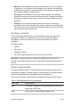
Content Introduction 3 Product overview 3 Features 4 Installation 4 Installation environment 4 Package contents 5 Cable requirements 5 Camera description 6 Setting up the camera 6 Connecting the devices 7 Accessing the SDHC card 9 Mounting the dome cameras on a ceiling 10 Mounting the wedge dome cameras on a ceiling 12 Using the camera with an Interlogix NVR or Hybrid DVR and other systems 14 Using the camera with TruVision Navigator 14 Specifications 14 TruVision Indoor IP Dome cameras 14 IP wedge dome cam
TruVision IP wedge dome: TVD-M1210W-2-N(-P) TVD-M1210W-2W-N(-P) TVD-N210W-4-N(-P) TVD-M2210W-4-N(-P) (1.3 megapixel) (1.3 megapixel) (VGA) (2 megapixel) Features This section describes the camera features.
• Moisture: Do not expose the camera to rain or moisture, or try to operate it in wet areas. Turn the power off immediately if the camera is wet and ask a qualified service person for servicing. Moisture can damage the camera and also create the danger of electric shock. • Servicing: Do not attempt to service this camera yourself. Any attempt to dismantle or remove the covers from this product will invalidate the warranty and may also result in serious injury.
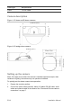
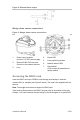
Cable type Requirements Power 12 VDC cable Camera description Figure 1: IP dome and IR dome cameras Figure 2: IP wedge dome camera Setting up the camera Note: If the light source where the camera is installed experiences rapid, widevariations in lighting, the camera may not operate as intended. To quickly put the dome camera into operation: 1. Prepare the mounting surface. 2. Connect the power cable (optional), alarm I/O cables, RS-485 cable, audio cables and network cable to the camera.
3. Mount the camera to the ceiling using the appropriate fasteners. See “Mounting the dome cameras on a ceiling” on page 10. 4. Set up the camera’s network and streaming parameters so that the camera can be controlled over the network. For further information, please refer to the “TruVision IP Camera Configuration Manual”. 5. Program the camera to suit its location. For further information, please refer to the “TruVision IP Camera Configuration Manual”.
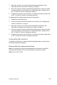
Figure 3: Connections on the base of the dome and IR dome cameras 1. Ground Connect to ground. 2. 6. Ethernet RJ45 PoE port Connect to network devices. RS-485 D+, DConnect to an RS-485 device such as a PTZ unit. 7. 3. Audio output Connect to an audio output. Line level, 600 Ω. Alarm outputs Connect 1A/1B and 2A/2B to alarm output devices. 8. 4. Initial set Press to reset all parameters to factory default. Alarm inputs Connect IN1/GND and IN2/GND to alarm input devices. 9.
Figure 4: External alarm output Wedge dome camera connections Figure 5: Wedge dome camera connections 1. 2. 3. Power input connector Connect +12 VDC power supply. Ethernet RJ45 PoE connector Connect to the network devices. Lens 4. Power LED 5. Lens positioning screws 6. Network status LEDs 7. Reset switch Click to reset all parameters to factory default.
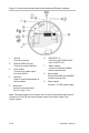
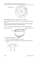
Figure 6: SDHC card slot location in the dome cameras SDHC card slot Mounting the dome cameras on a ceiling Mount the dome cameras on a ceiling. They are not recommended for mounting on a wall. Note: If required, cables can be feed through the sides of the dome housing by removing the tabs (1) using a pliers (see Figure 7 below). Figure 7: Creating cable access points in the dome housing (optional) To mount the dome camera on a ceiling: 1. Place the mounting plate (supplied) on the ceiling. 2.
3. In the middle of the mounting plate make a hole in the ceiling to access the cabling. 4. If needed, seal all mounting holes so that no moisture can leak into the mounting surface. 5. Insert the fixation pins of the dome camera housing into the fixation slots in the mounting plate (1). 6. Rotate the camera enclosure (2) so that the pins are held in place in the fixation slots. 7. Tighten the locking screw (3) to ensure that the camera is firmly attached to the bracket. 8.
RCA video output connector Video cable for testing (supplied) Lens adjustment screw 10. Remove the temporary video cable and reattach the camera cover. Tighten the fixed screws. Ensure that the camera is firmly attached to the mounting bracket. 11. Connect a 12 VDC power supply to the power cable. Mounting the wedge dome cameras on a ceiling Mount the wedge dome camera on a ceiling. It is not recommended for mounting on a wall. To mount the mini dome camera on a ceiling: 1.
3. Pull the camera’s cabling through the ceiling hole and connect to the devices and power. If needed, seal all mounting holes so that no moisture can leak into the mounting surface. 4. Adjust the camera’s angle of view while watching the image on a monitor. Loosen the lens positioning screws (1). Using the supplied hex wrench, adjust the camera pan and tilt horizontally and vertically. Tighten the lens positioning screws.
Using the camera with an Interlogix NVR or Hybrid DVR or another system Please refer to the NVR/DVR user manuals for instructions on connecting and operating the camera with these systems. Using the camera with TruVision Navigator A camera must be connected to an Interlogix NVR or hybrid DVR in order to be operated by TruVision Navigator. Please refer to the TruVision Navigator user manual for instructions on operating the camera with the TruVision Navigator.
Operating temperature -10 to +60°C (14 to 140°F) Environmental rating Indoor vandal-resistant PC requirements Intel-based PC 1 GHz or faster Memory I GB RAM Operating system Windows® XP, Vista or Windows 7 CGI Direct X 9.0 or later Browser Microsoft Internet Explorer 6.0 or later IP wedge dome cameras Electrical Voltage input 12 VDC, PoE (IEEE 802.3af) Power consumption 4 W max.
PC requirements Intel-based PC 1 GHz or faster Memory I GB RAM Operating system Windows® XP, Vista or Windows 7 CGI Direct X 9.0 or later Browser Microsoft Internet Explorer 6.0 or later Pin definitions There are eight wires on a standard UTP/STP cable and each wire is colorcoded.