TruVision IP Cam OpenStandards User Manual P/N 1076513A-EN • REV 1.
Copyright Trademarks and patents © 2011 UTC Fire & Security. All rights reserved. Interlogix, TruVision names and logos are trademarks of UTC Fire & Security. Other trade names used in this document may be trademarks or registered trademarks of the manufacturers or vendors of the respective products. Manufacturer UTC Fire & Security Americas Corporation, Inc. 2955 Red Hill Avenue, Costa Mesa, CA 92626-5923, USA Authorized EU manufacturing representative: UTC Fire & Security B.V.
Content Chapter 1 Introduction 1 Product overview 1 Features 1 Chapter 2 Installation 3 Installation environment 3 Package contents 4 Cable requirements 4 Camera description 5 Connections 6 Accessing the SDHC card 7 Setting up the camera 7 Mounting the camera on a ceiling 8 Using the camera with TVR 60/ TVN 20/ TVN 40/ LNVR and other systems 9 Using the camera with TruVision Navigator 9 Chapter 3 Network and streaming configuration 11 Checking your Web browser security level 11 Accessing the camera ov
Chapter 6 Camera operation 43 Logging on and off 43 Live mode 43 Playing back recorded video 44 Searching event logs 46 Archiving recorded files 48 Using presets 49 Appendix A Specifications 51 Appendix B Pin definitions 53 Appendix C Warranty and contact information 55 Warranty information 55 Contacting support 55 Index 57 ii TruVision IP Cam Open-Standards User Manual
Chapter 1 Introduction Product overview This is the user manual for TruVision IP Cam Open-Standards camera models: - TVC-N220-1-N(-P) (VGA) - TVC-N240-1-N(-P) (4CIF WDR) - TVC-M1220-1-N(-P) (1.3 megapixel) - TVC-M2220-1-N(-P) (2.0 megapixel) - TVC-M3220-1-N(-P) (3.0 megapixel) - TVC-M5220-1-N(-P) (5.0 megapixel) Features This section describes the camera features.
0BChapter 1: Introduction 2 TruVision IP Cam Open-Standards User Manual
Chapter 2 Installation This chapter provides information on how to install the cameras. Installation environment When installing your product, consider these factors: • Electrical: Install electrical wiring carefully. It should be done by qualified service personnel. Always use a proper PoE switch or a 12 VDC UL listed Class 2 or CE certified power supply to power the camera. Do not overload the power cord or adapter.
1BChapter 2: Installation Package contents Check the package and contents for visible damage. If any components are damaged or missing, do not attempt to use the unit; contact the supplier immediately. If the unit is returned, it must be shipped back in its original packaging.
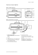
1BChapter 2: Installation Camera description Figure 1: Camera dimensions Figure 2: Side elevation of the camera 1. Bracket mounting holes. 6. Auto iris lens connector. Can be repositioned to the other side of the Video-type auto iris lens connection: camera. A. Power; B. NC (no connection); C. GND; 2. Camera. D. Video 3. C-mount adaptor (for C-mount lenses only). 4. Lens (auto iris lens shown. A manual iris has no cable.)Not included. DC-type auto iris lens connection: A. Damping coil (-); B.
1BChapter 2: Installation Connections A qualified service person, complying with all applicable codes, should perform all required hardware installation. Note: Do not attempt to extend the power/data cable connection using RJ45 couplers and Cat5 cable. Only use the data cable connection provided. Note: Use 12 VDC or PoE. Figure 3: Wiring the camera 1. Ethernet RJ45 PoE port Connect to network devices. 6. Power supply Connect +12 VDC power supply. 2. Video output Connect to a CCTV monitor. 7.
1BChapter 2: Installation Figure 4: External alarm output Accessing the SDHC card Insert an SDHD car dup to 32GB for local storage as a backup in case the network fails, for example (see Figure 5 below). The card is not supplied with the camera. Video and log files stored on the SDHC card can only be accessed via the Web browser. You cannot access the card using TruVision Navigator or TVR 60.
1BChapter 2: Installation 4. Connect the cables to the camera. See “Connections” on page 6. 5. Set up the camera’s network and streaming parameters so that the camera can be controlled over the network. See Chapter 3 Network and streaming configuration” on page 11. 6. Program the camera to suit its location. See “Chapter 4 Camera configuration” on page 23. Mounting the camera on a ceiling Mount the camera on a ceiling. It is not recommended for mounting on a wall.
1BChapter 2: Installation 7. Adjust the camera position and angle as required. 8. Connect a lens to the camera. For optimal performance, use an autoiris lens. Using the camera with TVR 60/ TVN 20/ TVN 40/ LNVR and other systems Please refer to the head-end user manuals for instructions on connecting and operating the camera with these systems. Using the camera with TruVision Navigator A camera must be connected to a TVR 60/ TVN 20/ TVN 40 in order to be operated by TruVision Navigator.
1BChapter 2: Installation 10 TruVision IP Cam Open-Standards User Manual
Chapter 3 Network and streaming configuration This chapter explains how to configure the camera network settings. The cameras can be configured and controlled using an internet browser such as Microsoft Internet Explorer (IE). The procedures described use Microsoft Internet Explorer (IE) web browser. The steps are similar with other browsers. You must have administrator rights on your PC in order to configure the cameras over the internet.
2BChapter 3: Network and streaming configuring 4. Change the ActiveX controls and plug-ins options to Enable and click OK. - or Under Reset Custom Settings, click the security level for the whole zone in the Reset To box, and select Low. Click Reset. Then click OK to the Internet Options Security tab screen. 5. Click Apply in the Internet Options Security tab screen.
2BChapter 3: Network and streaming configuring Windows Vista and 7 users Internet Explorer for Windows Vista and Windows 7 operating systems have increased security measures to protect your PC from any malicious software being installed.
2BChapter 3: Network and streaming configuring Click OK. The Web browser screen appears in live mode. Note: You can stop and start live view by clicking the Start/stop live view button on the bottom of the screen. Overview of the camera Web browser The camera Web browser lets you view, record, and play back recorded videos as well as manage the camera from any PC with Internet access. The browser’s easy-to-use controls give you quick access to all camera functions. See Figure 6 on page 15.
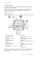
2BChapter 3: Network and streaming configuring Figure 6: Web browser interface Item Name Description 1. PTZ controls For future use. 2. Live view Click to view live video. 3. Playback Click to play back video. 4. Log Click to search for event logs. There are four main information types: All, Alarm, Notification and Operation Note: The Playback and Log functions can only be used when an SDHC card is inserted in the camera. 5.
2BChapter 3: Network and streaming configuring Item Name Description 13. Video image settings Click the required icon in the pop-up window and then slide the bar to adjust video image settings such as brightness, contrast, saturation, hue and exposure time (exposure time is equivalent to shutter speed). Changes appear immediately and are also applied to the settings in the menu “Camera image settings” (see page 34). Click settings. 14. e-PTZ to return to default Click to enable/disable e-PTZ.
2BChapter 3: Network and streaming configuring Figure 7: Example of a configuration screen (Local configuration shown) Configuration panel Menu screen Current user displayed Exit system Save changes There are two main folders in the configuration panel: Local configuration Remote configuration Local configuration Use the Local menu to manage the network type, display mode and local storage paths. In the Configuration panel, click “Local configuration” to display the Local settings screen.
2BChapter 3: Network and streaming configuring Parameters Description Save captured picture as Specifies the directory for saving snapshot files. The default directory is C:\Program Data\Web\BMPCaptureFiles. Save playback captured picture as Specifies the directory for saving playback files. The default directory is C:\Program Data\Web\PlaybackFiles. Save download file as Specifies the directory for downloaded files. The default directory is C:\Program Data\Web\DownloadFiles.
2BChapter 3: Network and streaming configuring Configuration folders Description Serial settings Defines the RS-485 and RS-232 communication settings. See “Serial port settings” on page 21. Alarm parameters Defines how the camera handles alarms such as input type, notification of alarms, and response schedules and duration. See “Alarm parameters” on page 26. Deployment time Defines the schedules during which events are registered. See “Events scheduling” on page 27.
2BChapter 3: Network and streaming configuring Figure 9: Network subfolder screen (to be updated - no NFS) Table 4: Network parameters Parameters Description Network NIC type: Specifies the NIC type. Default is 10M/100M Auto. Other options include: 10M half-dup, 10M full-dup, 100M half-dup and 100M full-dup and 10M/100M auto. Default is 10M/100M. IP address: Specifies the IP address of the camera. Subnet mask: Specifies the subnet mask. Default value is 255.255.255.0.
2BChapter 3: Network and streaming configuring To define the network parameters: 1. In the “Network Parameters” folder click the Network setting subfolder to open its screen. From the NIC Type drop-down list, select the required value. Enter the values for the IP address, subnet mask, gateway, DNS server and HTTP port. Click Save to save changes. 2. Click the PPPoE setting subfolder to open its screen and check Enable PPPoE. Enter the user name and password. Click Save to save changes. 3.
2BChapter 3: Network and streaming configuring Figure 10: RS-485 setting menu Note: When a parameter is modified in either of these menus, the camera will prompt you to save and reboot. Table 5: RS-232 and RS-485 settings Item Description Bits per second Default baud rate value for the RS-232 port is 9600. Default baud rate value for the RS-485 port is 9600. Data bits Default value is 8. Stop bits Default value is 1. Parity Default value is “None”.
Chapter 4 Camera configuration This chapter explains how to configure the camera through a Web browser. You must have administrator rights on your PC in order to configure the camera over the internet. Camera parameters This section describes how to configure the camera settings from the Channel Parameter screen. There are eight subfolders, which are described below: • Display settings: Defines how the date and time are displayed on screen.
3BChapter 4: Configuring the camera All changes made apply only to the camera being configured. Parameters cannot be copied to another camera. Note: When schedule parameters are modified, the camera will prompt you to reboot after the changes are saved. Figure 11: Channel parameters folder (Display setting menu shown) Defining how information is displayed on screen In addition to the camera name, the camera also displays the system date and time on screen.
3BChapter 4: Configuring the camera 5. Select the time format from the Time format list box. Formats include: 24hour and 12-hour. 6. Select a display mode for the camera from the OSD Status list box. Display modes include: • Transparent & Non-Flashing. The screen image appears through the text. This is default. • Transparent & Flashing. The screen image appears through the text. The text flashes on and off. • Non-Transparent & Non-Flashing. The screen image is behind the text.
3BChapter 4: Configuring the camera 4. Click Save to save changes. Alarm parameters Use this menu to select how external alarm inputs and alarm outputs should be handled. Figure 12: Alarm input screen To set up an external alarm input: 1. In the “Alarm Parameters” folder click the Alarm Input subfolder to open its screen. 2. Select t one of the external alarm inputs from the Alarm input drop-down list, A1 or A2. 3. Select the input type in the Relay status box. Alarm input type refers to the sensor type.
3BChapter 4: Configuring the camera 5. Click Save to save changes. Note: The camera will prompt you to reboot in order for the schedule changes to take effect. To set up an alarm relay output: 1. In the “Alarm Parameters” folder open the Alarm Output screen. 2. Select one of the alarm outputs from the Alarm output drop-down list, A1 or A2. 3. Select the alarm output delay time. The alarm output delay is the length of time during which the relay is operational after the alarm occurs.
3BChapter 4: Configuring the camera Figure 13: Deployment time menu To define an event schedule: 1. Click the “Deployment” folder to open its screen. 2. Under “Event type” select the option to be scheduled from the dropdown list. There are five options: Motion detection, input port 1, input port 2, output port 2 and output port 2. 3. Select the day of the week and the time period for the event schedule. The time periods must not overlap. 4. Select another day of the week to set up its event schedule.
3BChapter 4: Configuring the camera Figure 14: Video setting menu Parameter Description Channel name Name of the camera Encoding parameters Specifies the dual streaming method used. Options include: Main stream and sub stream. Default is Main. Stream type Specifies the stream type you wish to record. Select Video to record video stream only. Select Video&Audio to record both video and audio streams. Default value is Video&Audio. Resolution Specifies the recording resolution.
3BChapter 4: Configuring the camera Parameter Description Frame rate Specifies the frame rate for the selected resolution. The frame rate is the number of video frames that are shown or sent per second. Default value is 25 (PAL)/ 30 (NTSC). I frame interval A video compression method. It is strongly recommended not to change the default value displayed: 25. Multicast address Specifies a D-class IP address between 224.0.0.0 to 239.255.255.255.
3BChapter 4: Configuring the camera 5. If you selected “All day recording”, select one of the record types to record from the drop-down list box: • Schedule recording. This is continuous recording. • Motion detection • Alarm record • Motion or alarm • Motion and alarm - Or If you selected “Section recording”, in the left column click the day of the week required and then set the start and end times for each section (time period) during which you want the camera to begin and end recording.
3BChapter 4: Configuring the camera Select the level of sensitivity to motion as well as the target size so that only objects that could be of interest can trigger a motion recording. For example, the motion recording is triggered by the movement of a person but not that of a cat.
3BChapter 4: Configuring the camera To define the motion detection areas and response method: Note: The deployment and motion detection recording schedules must also be defined for motion to be detected and recorded. See “Events scheduling” on page 26 and “Defining a recording schedule” on page 30. 1. In the Channel Parameters folder click the Motion detection subfolder to open its screen. 2. Check the Enable Motion Detection box.
3BChapter 4: Configuring the camera Email link Sends an e-mail to a specified address when there is a motion detection alarm. See “Network parameters” on page 19 for further information. You can send an attachment with the e-mail. Trigger alarm output Triggers the camera’s alarm output. Up to two alarm outputs can be selected. Trigger recording Triggers the recording to start in the camera (A1). 7. Click Save to save changes.
3BChapter 4: Configuring the camera Figure 16: Camera image settings menu (4CIF camera screen shown) Parameter Description Brightness Video saturation Sharpness Modifies the different elements of picture quality by adjusting the position of the values for each of parameter. Shutter The shutter speed controls the length of time that the aperture is open to let light into the camera through the lens. Select a higher value to see movement and a lower value to see clearer images.
3BChapter 4: Configuring the camera Parameter Description WDR level 1 WDR level 2 4CIF camera models only. When enabled, this feature (wide dynamic range) allows you to see details of objects in shadows or details of objects in bright areas of frames that have high contrast between light and dark areas. Use these two scroll bars to adjust the WDR level. WDR contrast level 4CIF camera models only. Adjusts the WDR contrast level. BLC All camera models except the 2 megapixel camera.
Chapter 5 Camera management This chapter describes how to use the camera once it is installed and configured. The camera is accessed through a Web browser. User management This section describes how to manage users from the “User Management” screen. You can: Add or delete users Modify passwords Only the administrator can manage users. The administrator can create up to 15 additional individual users.
4BChapter 5: Camera management Note: Keep the admin password in a safe place. If you should forget it, contact technical support. You can control who can connect to a camera by the user IP and physical (MAC) addresses entered for a user. Setting up a user with a MAC address from the user’s computer prohibits access to the camera from other computers. All users can connect to a camera when IP and MAC addresses are set to zero. The user access rights must be set up for each camera individually.
4BChapter 5: Camera management 7. Click OK to save the changes and return to the main “User management” screen. To delete a user: 1. Click the User management folder to open its screen. 2. Select the Delete button. The user management screen appears. 3. Click the desired user in the list. Select Delete. Confirm that you want to delete the user. 4. Click OK to save the changes. Modifying user information You can easily change the information about a user such as their name, password or computer ID.
4BChapter 5: Camera management To format the SDHC card: 1. Click the HDD Management folder to open its screen. 2. Click Select All in the HDD Number column to select the SDHC card. Only one HDD option is listed. 3. Click Format. A screen appears showing the formatting status. Restoring default settings Use the Default menu to restore default settings to the camera. There are two options available: Full mode: All parameters are restored to factory default settings.
4BChapter 5: Camera management To upgrade the firmware through the Web browser: 1. Download on to your computer the latest firmware from our web site at: www.utcfssecurityproductspages.eu/videoupgrades/ 2. In the “Remote configuration” folder select the subfolder “Remotely upgrade” to open the “Remotely upgrade” screen. 3. Click the Browse button to locate the latest digicap.DAV file on your computer. 4. Click Update. You will receive a prompt asking you to reboot the camera.
4BChapter 5: Camera management 42 TruVision IP Cam Open-Standards User Manual
Chapter 6 Camera operation This chapter describes how to use the camera once it is installed and configured. Logging on and off You can easily login and out of the camera browser screen by clicking the Login button on the menu toolbar. You will be asked each time to enter your user name and password when logging in. Figure 18: Login dialog box Only one camera is accessible from a Web browser screen.
5BChapter 6: Camera operation Adjusting the image quality Click the image quality button in the live mode screen to get a pop-up window that lets you adjust video image settings such as brightness, contrast, saturation, hue and exposure time (see Figure 6 on page 15). Changes appear immediately and are also applied to the settings in the menu “Camera image settings” (see page 34). Manual recording You can manually record live video and store the images on your computer’s desk top.
5BChapter 6: Camera operation Figure 19: Playback screen Item Name Description 1. Playback button Click to open the Playback screen. 2. Full screen Click to view as full screen. 3. Current status Displays recording type currently being played. 4. Search calendar Click the day required to search. You cannot search by particular criteria such as alarm type or time. However, the type of recording is displayed in the recording type bar (see item 9).
5BChapter 6: Camera operation Item Name Description 11. Recording type The color code displays the recording type. Recording types are schedule recording, alarm recording and manual recording. The recording type name is also displayed in the current status window. 12. Archive functions Click these buttons for the following archive actions: Capture a snapshot image of the playback video. Save the selected file onto your desktop. 13. Audio Adjust the audio level.
5BChapter 6: Camera operation Figure 20: Log screen 1. Logs type 4. Start search 2. Date search 5. Export log. Save selected logs to your computer desktop. 3. Start and end search times You can search for recorded logs by the following criteria: Log type: There are three types of logs: Alarm, Notification and Operation. See Table 6 below for their descriptions. Date: Logs can be searched by date. Time: Logs can be searched by start and end recording times.
5BChapter 6: Camera operation To search logs by type: 1. Click Log in the menu toolbar to display the Log screen. 2. In the Log Type drop-down list select the desired option. 3. Click Search to start your search. The results appear in the screen. To search logs by date and time: 1. Click Log in the menu toolbar to display the Log screen. 2. Select a date to be searched. Only one day can be searched at a time. 3. Enter a start and end time. 4. Click Search to start your search.
5BChapter 6: Camera operation 2. Repeat step 1 to create additional segments. You can generate up to 30 additional segments. The video segments are saved onto your computer desktop. Using presets This function is for future use.
5BChapter 6: Camera operation 50 TruVision IP Cam Open-Standards User Manual
Appendix A Specifications Electrical Voltage input 12 VDC, PoE (IEEE 802.3af) Power consumption 4.5 W max. TVC-N220-1-N(-P), TVC-M2220-1-N(-P) 5 W max. TVC-M5220-1-N(-P) 5.5 W max. TVC-N240-1-N(-P), TVC-M3220-1-N(-P) 7.5 W max. TVC-M1220-1-N(-P) I/O connection Terminal plug, RJ45 flying lead Network Protocols TCP/IP, HTTP, DHCP, DNS, DDNS, RTP/RTCP, PPPoE, SMTP, NTP Ethernet/IP CoS 802.1 p/Q, QoS, IPv4 PoE IEEE 802.3af Miscellaneous Dimensions (D × H) 68 x 57 x 144 mm (2.68 x 2.24 x 5.70 in.
6BAppendix A: Specifications 52 TruVision IP Cam Open-Standards User Manual
Appendix B Pin definitions There are eight wires on a standard UTP/STP cable and each wire is colorcoded.
7BAppendix B: Pin definitions Please make sure your connected cables have the same pin assignment and color as above before deploying the cables in your network.
Appendix C Warranty and contact information Warranty information The warranty period for the TruVision IP Cam Open-Standards is three years from the date of delivery. Contacting support For help installing, operating, maintaining, and troubleshooting this product, refer to this document and any other documentation provided. If you still have questions, contact us during business hours (Monday through Friday, excluding holidays). Note: Please be ready at the equipment before calling.
8BAppendix C: Warranty and contact information 56 TruVision IP Cam Open-Standards User Manual
Index A Alarm configuration, 26 response method, 26 Alarm inputs configuration, 26 Alarm outputs configuration, 26 Alarm settings alarm relay output, 27 Alarm types motion detection, 31 Archived files playing back, 48 Archiving files recorded files, 48 set up default directories, 17 snapshots of recorded files, 48 B restore, 40 Device information display, 19 Display information on-screen set up, 24 E E-mail setup alarm response method, 26 configuring, 21 Events schedule defining, 27 Exposure time setup,
Index M Motion detection configuring, 31 marking the detection areas, 33 N Network parameters, 19 Network protocol setup, 17 Network settings configuring, 16, 20 overview of local camera parameters, 17 NTP synchronization, 25 P Passwords modifying, 39 Playback play back recorded files, 46 screen, 44 searching recorded video, 44 Post-event recording times description, 30 main/sub setup, 17 System time set up, 25 T Text adding extra lines of text on screen, 34 Text display on-screen appearance, 24 Time f