TruVision IP Camera Configuration Manual Firmware 5.0X P/N 1072665A-EN • REV 1.
Copyright © 2013 UTC Fire & Security Americas Corporation, Inc. Interlogix is part of UTC Climate Controls & Security, a unit of United Technologies Corporation. All rights reserved. Trademarks and patents The TruVision and Interlogix names and logos are trademarks of United Technologies. Other trade names used in this document may be trademarks or registered trademarks of the manufacturers or vendors of the respective products. Manufacturer UTC Fire & Security Americas Corporation, Inc.
Content Chapter 1 Introduction 1 Chapter 2 Network access 3 Checking your web browser security level 3 Accessing the camera over the internet 5 Overview of the camera web browser 5 Chapter 3 Camera configuration 9 Configuration 9 Local configuration 10 System time 12 Network settings 13 Recording parameters 17 Video image 18 OSD 21 Overlay text 22 Privacy masks 23 Motion detection alarms 23 Tamper-proof alarms 26 Exception alarms 27 Alarm inputs and outputs 27 Snapshot parameters 28 NAS settings 29 Sto
Index 49 ii TruVision IP Camera Configuration Manual
Chapter 1 Introduction This is the user manual for TruVision IP camera models: TVB-1101 (1.3MPX IP bullet camera, PAL) TVB-3101 (1.3MPX IP bullet camera, NTSC) TVB-1102 (3MPX IP bullet camera, PAL) TVB-3102 (3MPX IP bullet camera, NTSC) TVD-1103 (1.3MPX IP VF mini dome, PAL) TVD-3103 (1.3MPX IP VF mini dome, NTSC) TVD-1104 (3MPX IP VF mini dome, PAL) TVD-3104 (3MPX IP VF mini dome, NTSC) TVD-1101 (1.3MPX IP indoor mini dome, PAL) TVD-3101 (1.
0BChapter 1: Introduction 2 TruVision IP Camera Configuration Manual
Chapter 2 Network access This manual explains how to configure the camera over the network with a web browser. TruVision IP cameras can be configured and controlled using Microsoft Internet Explorer (IE) and other browsers. The procedures described use Microsoft Internet Explorer (IE) web browser. Checking your web browser security level When using the web browser interface, you can install ActiveX controls to connect and view video using Internet Explorer.
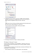
1BChapter 2: Network access 4. Change the ActiveX controls and plug-ins options that are signed or marked as safe to Enable. Change the ActiveX controls and plug-ins options that are unsigned to Prompt or Disable. Click OK. - or Under Reset Custom Settings, click the security level for the whole zone in the Reset To box, and select Medium. Click Reset. Then click OK to the Internet Options Security tab window. 5. Click Apply in the Internet Options Security tab window.
1BChapter 2: Network access • Add the camera’s IP address to your browser’s list of trusted sites To add the camera’s IP address to Internet Explorer’s list of trusted sites: 1. Open Internet Explorer. 2. Click Tools, and then Internet Options. 3. Click the Security tab, and then select the Trusted sites icon. 4. Click the Sites button. 5. Clear the “Require server verification (https:) for all sites in this zone box. 6. Enter the IP address in the “Add this website to the zone” field. 7.
1BChapter 2: Network access If there is more than one camera connected over the network, open a separate web browser window for each individual camera. Figure 1: Web browser interface Table 1: Overview of the web browser interface No. Name Description 1. Live view Click to view live video. 2. Playback Click to play back video. 3. Log Click to search for event logs. There are three main types: Alarm, Exception and Operation. 4.
1BChapter 2: Network access No. Name Description 12. Digital Zoom Click to enable digital zoom. 13. Bidirectional audio Turn on/off microphone. 14. Audio Adjust volume.
1BChapter 2: Network access 8 TruVision IP Camera Configuration Manual
Chapter 3 Camera configuration This chapter explains how to configure the cameras through a web browser. Once the camera hardware has been installed, configure the camera’s settings through the web browser. You must have administrator rights in order to configure the cameras over the internet. The camera web browser lets you configure the camera remotely using your PC. Web browser options may vary depending on camera model. The camera is configured using on-screen display (OSD) menus.
2BChapter 3: Camera configuration Figure 2: Configuration panel (Device Information tab selected) Table 2: Overview of the Configuration panel No. Configuration folders Description 1. System Defines device basic information including SN and the current firmware version, time settings, maintenance, and serial port parameters. 2. Network Defines the network parameters required to access the camera over the internet. 3. Video/Audio Defines recording parameters. 4.
2BChapter 3: Camera configuration Figure 3: Example of a configuration window (Local configuration shown) Table 3: Overview of the Local configuration window No. Parameters Description Live View Parameters 1. Protocol Specifies the network protocol used. Options include: TCP, UDP, MULTICAST and HTTP. 2. Live View Performance Specifies the transmission speed. Options include: Least Delay, Balanced or Best Fluency. Record File Settings 3. Record File Size Specifies the maximum file size.
2BChapter 3: Camera configuration System time NTP (Network Time Protocol) is a protocol for synchronizing the clocks of network devices, such as IP cameras and computers. Connecting network devices to a dedicated NTP time server ensures that they are all synchronized. To define the system time and date: 1. In the System folder, click the Time Settings tab to open its window. 2. From the Time Zone drop-down menu, select the time zone that is the closest to the camera’s location. 3.
2BChapter 3: Camera configuration Network settings Accessing the camera through a network requires that you define certain network settings. Use the “Network” folder to define the network settings. See Figure 4 and Table 4 below for further information. Figure 4: Network window (TCP/IP tab shown) Table 4: Network parameters No. Parameters Description 1. NIC Type: Specifies the NIC type. Default is Auto. Other options include: 10M Half-dup, 10M Full-dup, 100M Half-dup and 100M Full-dup.
2BChapter 3: Camera configuration No. Parameters Description 2. Port HTTP Port: Specifies the port used for the Internet Explorer (IE) browser. Default value is 80. RTSP Port: Specifies the RTSP port. The default port number is 554. HTTPS Port: Specifies the HTTPS port. The default port number is 443. SDK Port: Specifies the SDK port. The default port number is 8000. 3. DDNS Specifies IP server, DynDNS and ezDDNS. 4. PPPoE Use this option to retrieve a dynamic IP address. 5.
2BChapter 3: Camera configuration 4. Click Save to save changes. To define the PPPoE parameters: 1. In the Network folder, click the PPPoE tab to open its window. 2. Check Enable PPPoE to enable this feature. 3. Enter User Name, Password, and Confirm password for PPPoE access. 4. Click Save to save changes. To define the SNMP parameters: Note: Before setting the SNMP, please download the SNMP software and manage to receive the camera information via the SNMP port.
2BChapter 3: Camera configuration To define the FTP parameters: 1. In the Network folder click the FTP tab to open its window. 2. Configure the FTP settings, including server address, port, user name, password, directory, and upload type. Directory: In the Directory Structure field, you can select the root directory, parent directory and child directory.
2BChapter 3: Camera configuration Recording parameters You can adjust the video and audio recording parameters to obtain the picture quality and file size best suited to your needs. Figure 5 and Table 5 below list the video and audio recording options you can configure for the camera. Figure 5: Video/Audio Settings menu (Video tab shown) Table 5: Video setting parameters No. Parameter Description 1. Stream Type Specifies the dual streaming method used.
2BChapter 3: Camera configuration No. Parameter Description 6. Frame Rate Specifies the frame rate for the selected resolution. The frame rate is the number of video frames that are shown or sent per second. Note: The maximum frame rate depends on the camera model and selected resolution. Please check the camera specifications in its datasheet. 7. Max bit rate Specifies the maximum allowed bit rate. A high image resolution requires that a high bit rate must also be selected.
2BChapter 3: Camera configuration Figure 6: Camera image settings menu Table 6: Image parameters No. Parameter Description 1. Brightness, Contrast Saturation, Hue, Sharpness Modifies the different elements of picture quality by adjusting the position of the values for each of parameter. 2. Exposure Time The exposure time controls the length of time that the aperture is open to let light into the camera through the lens.
2BChapter 3: Camera configuration No. Parameter Description 8. Use this function to flip the original image into a mirror image. This could be used, for example, when the camera needs to be installed upside down. The image can be flipped horizontally (up/down), vertically (right/left) or centered. Default is Close. Mirror Note: The on-screen text does not flip. 9.
2BChapter 3: Camera configuration OSD In addition to the camera name, the camera also displays the system date and time on screen. You can also define how the text appears on screen. To position the date/time and name on screen: 1. In the Image folder (1), click the OSD Settings tab (2) to open its window. 2. Check the Display Name box (3) to display the camera’s name on screen. You can modify the default name in the text box of Camera Name. 3.
2BChapter 3: Camera configuration Note: 1. If you set the display mode as transparent, the text varies according the background. With some backgrounds, the text may be not easily readable. 2. When you enable motion detection, it is recommended not to select the flickering display option as overlay text may trigger a motion alarm. Overlay text You can add up to four lines of text on screen. This option can be used, for example, to display emergency contact details.
2BChapter 3: Camera configuration Privacy masks Privacy masks let you conceal sensitive areas (such as neighboring windows) to protect them from view on the monitor screen and in the recorded video. The masking appears as a blank area on screen. You can create up to four privacy masks per camera. Note: There may be a small difference in size of the privacy mask area depending on whether local output or the web browser is used. Figure 8: Privacy mask menu To add privacy mask area: 1.
2BChapter 3: Camera configuration Select the level of sensitivity to motion as well as the target size so that only objects that could be of interest can trigger a motion recording. For example, the motion recording is triggered by the movement of a person but not that of a cat.
2BChapter 3: Camera configuration To set up motion detection: 1. In the Configuration > Events folder, click the Motion Detection tab to open its window. 2. Check the Enable Motion Detection box. Check Enable dynamic analysis for motion if you want to see where has motion real-time. Note: Deselect the “Enable Motion Detection” option to disable the motion detection alarm. 3. Click Draw Area. Click and drag the mouse on the live video image to draw an area sensitive to motion detection.
2BChapter 3: Camera configuration Trigger Channel Triggers the recording to start in the camera. Trigger Alarm Output Trigger external alarm outputs when an event occurs. Note: This option is only supported by cameras that support alarm output. 10. Click Save to save changes. Tamper-proof alarms You can configure the camera to trigger an alarm when the lens is covered and to take an alarm response action. To set up tamper-proof alarms: 1.
2BChapter 3: Camera configuration 8. Click Save to save changes. Exception alarms You can set up the camera to notify you when irregular events occur and how you should be notified. These exception alarms include: • HDD Full: All recording space of NAS is full. • HDD Error: Errors occurred while files were being written to the storage, no storage or storage had failed to initialize. • Network Disconnected: Disconnected network cable. • IP Address Conflicted: Conflict in IP address setting.
2BChapter 3: Camera configuration 3. Click Edit to set the arming schedule for the alarm input. See “To set up motion detection” for more information. 4. Check the checkbox to select the linkage method. 5. Click Save to save changes. To define alarm output: 1. In the Events folder, click the Alarm Output tab to open its window. 2. Select one alarm output channel from the Alarm Output drop-down list. You can also set a name for the alarm output. 3.
2BChapter 3: Camera configuration Note: If you have configured the FTP settings and check Upload Picture in the FTP tab, the snapshots will be uploaded to the FTP. If you also check Upload Snapshot for motion detection or alarm input, the snapshots will be uploaded to the FTP when motion detection or an alarm input is triggered. To set up snapshots: 1. In the Events folder, click the Snapshot tab to open its window. 2. Check Enable Timing Snapshot to enable continuous snapshots.
2BChapter 3: Camera configuration To set up a NAS system: 1. In the Storage folder, click the NAS tab to open its window. 2. Enter the IP address of the network disk, and the NAS folder path. 3. Click Save to save changes. Storage devices Use the storage management window to display the capacity, free space available and the working status of the HDD of the NAS and the SD card in the camera. You can also format these storage devices. Before formatting the storage device, stop all recording.
2BChapter 3: Camera configuration Pre-record time The pre- record time is set to start recording before the scheduled time or the event. For example, if an alarm triggers recording at 10:00, and the pre-record time is set as 5 seconds, the camera starts to record at 9:59:55. The pre-record time can be configured as No Pre-record, 5 s, 10 s, 15 s, 20 s, 25 s, 30 s, or not limited. Post- record time The post-record time is set to stop recording after the scheduled time or the event.
2BChapter 3: Camera configuration • Motion & Alarm: The video is recorded when motion and alarms are triggered at the same time. 5. If you selected “Customize”, click the day of the week required and then for period 1 set the start and end times during which you want the camera to begin and end recording. From the drop-down list box, select one of the record types to record. Repeat for additional periods in the day. Up to four time periods can be selected. Note: The four time periods cannot overlap. 6.
: Camera configuration To set up the RS-232 settings: 1. In the System folder, click the RS232 tab to open its window. 2. Select the RS-232 port parameters. Note: If you want to connect the camera using the RS-232 port, the RS-232 parameters must be the same as those configured here. 3. Click Save to save changes. RS-485 settings The RS-485 serial port is used to control the PTZ of the camera or connect to light and wiper devices.
: Camera configuration 34 TruVision IP Camera Configuration Manual
Chapter 4 Camera management This chapter describes how to use the camera once it is installed and configured. The camera is accessed through a web browser. User management This section describes how to manage users. You can: Add or delete users Modify permission Modify passwords Only the administrator can manage users. The administrator can create up to 31 individual users for the cameras listed in this manual.
3BChapter 4: Camera management There is no default password provided for all users. Users can not modify their password, and only the administrator can create or modify password for a user. Note: Keep the admin password in a safe place. If you forget it, please contact technical support. Types of users A user’s access privileges to the system are automatically defined by their user type. There are three types of user: Admin: This is the system administrator. The administrator can configure all settings.
3BChapter 4: Camera management 6. Assign permissions to users. 7. Click OK to save the settings. To delete a user: 1. Select one user in the User tab. 2. Click Delete button. A message box appears. Note: Only the administrator can delete a user. 3. Click Save to save the changes. Modify user information You can easily change the information about a user such as their name, password and permissions. To modify user information: 1. Select one user in the User tab. 2. Click the Modify button.
3BChapter 4: Camera management 2. Select the Authentication type Enable or Disable in the drop-down list to enable or disable the RTSP authentication. 3. Click Save to save the changes. Note: If "RTSP Authentication" is disabled, although the user has no permission for “Remote: Live View", he can still see the live view images. IP address filter This function makes it possible for access control. To define IP Address Filter: 1. In the Configuration folder, select the Security tab. 2.
3BChapter 4: Camera management Note: Video standard cannot be restored to default settings no matter Restore or Default. To restore default settings: 1. In the Configuration folder, select the System tab. 2. Select the Maintenance tab. 3. Click either Restore or Default. A window showing user authentication appears. 4. Enter the admin password and click OK. 5. Click OK in the pop-up message box to confirm restoring operation. Import/export a configuration file To import/export configuration file: 1.
3BChapter 4: Camera management 3. In the Maintenance tab, click the Browse button to locate the firmware file on your computer. Note: Please select utc_amb_ipc.dav for product models listed in Chapter 1 on page 1, and utc_365_ipc.dav for TruVision IP open standard cameras. 4. Click Update. You will receive a prompt asking you to reboot the camera. 5. The upgrading process will take several minutes. When the upgrade is finished, the device will reboot automatically. 6.
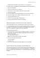
Chapter 5 Camera operation This chapter describes how to use the camera once it is installed and configured. Logging on and off You can easily log out of the camera browser window by clicking the Logout button on the menu toolbar. You will be asked each time to enter your user name and password when logging in. Figure 14: Login dialog box Live view mode Once logged in, click “Live View” on the menu toolbar to access live view mode. See Figure 1 on page 6 for the description of the interface.
4BChapter 5: Camera operation Take a snapshot: You can take a snapshot of a scene when in live view. Simply click the Capture button located at the bottom of the window to save an image. The image is in JPEG format. Snapshots are saved on the hard drive. Playing back recorded video You can easily search and play back recorded video in the playback interface. Note: You must configure NAS or insert SD card in the dome camera to be able to use the playback functions.
4BChapter 5: Camera operation No. Name Description 4. Set playback time Input the time and click point. 5. Control playback Click to control how the selected file is played back: play, stop, slow and fast forward playback. 6. Timeline bar The timeline bar displays the 24-hour period of the day being played back. It moves left (oldest) to right (newest). The bar is color-coded to display the type of recording.
4BChapter 5: Camera operation 2. Repeat step 1 to create additional segments. The video segments are saved on your computer. To archive recorded snapshots: 1. Click to open the snapshots search window. 2. Select the snapshot type as well as the start and end time. 3. Click Search to search for the snapshots. 4. Select the desired snapshots, and click Download to download them. Searching event logs You must configure NAS or insert a SD card in the dome camera to be able to use the log functions.
4BChapter 5: Camera operation Figure 16: Log window 1. Major Type 4. Start search 2. Minor Type 5. Save searched logs 3. Start and end search time You can search for recorded logs by the following criteria: Major type: There are three types of logs: Alarm, Exception, and Operation. You can also search All. See Table 7 below for their descriptions. Minor type: Each major type has some minor types. See Table 7 below for their descriptions.
4BChapter 5: Camera operation To search logs: 1. Click Log in the menu toolbar to display the Log window. 2. In the Major Type and Minor Type drop-down list, select the desired option. 3. Select start and end time of the log. 4. Click Search to start your search. The results appear in the left window. Operating PTZ control In the live view interface, you can use the PTZ control buttons to realize pan/tilt/zoom control and other functions of the camera.
4BChapter 5: Camera operation Note: 1. To realize pan/tilt movements using direction buttons, the camera connected to the network must support RS-485 and a pan/tilt unit must be installed to the camera. Please properly set the PTZ parameters on RS-485 Settings page referring to Defining RS-485 settings 2. To realize lens control, such as zoom or focus, the camera must support auto focus. To set a preset: 1. Select a preset number from the preset list. 2.
Index 8 E 802.
Index N NAS settings, 29 Network, 27 Network protocol setup, 9, 10 Network settings overview of local camera parameters, 9, 10 set up, 13 NTP synchronization, 12 NTSC format selecting, 19 P PAL format selecting, 19 Passwords modifying, 37 Playback play back recorded files, 43 screen, 42 searching recorded video, 42 Port parameters set up, 14 Post-recording times description, 31 PPPoE parameters set up, 15 Pre-recording times description, 31 Privacy masks, 23 PTZ control, 46 Q QoS parameters set up, 15 R