Simon XT Installation Manual P/N 466-2265 • REV G • OCT12
Copyright Disclaimer © 2012 UTC Fire & Security Americas Corporation, Inc. Interlogix is part of UTC Climate Controls & Security, a unit of United Technologies Corporation. All rights reserved. The information in this document is subject to change without notice.
License All rights to and in the Licensed Product, including, but not limited to, copyrights, patents, trademarks, and trade secrets, belong to UTC FIRE & SECURITY, and UTC FIRE & SECURITY retains title to each copy of the Software. You agree that UTC FIRE & SECURITY at any time, upon reasonable notice, may audit Your use of the Software for compliance with the terms and conditions of this Agreement.
Limited warranty UTC FIRE & SECURITY warrants that for one (1) year from the date of delivery of the Licensed Product (Software Warranty Period), the functions contained in the Software will be fit for their intended purpose as described in the applicable Documentation from UTC FIRE & SECURITY, and will conform in all material respects to the specifications stated in such Documentation. UTC FIRE & SECURITY does not warrant that the operation of the Software will be uninterrupted or error-free.
Restricted rights legend The Licensed Product is provided with RESTRICTED RIGHTS. In the event the United States Government or an agency thereof is granted a license, the following additional terms apply: Restricted Computer Software, as defined in the Commercial Computer Software–Restricted Rights clause at Federal Acquisition Regulations 52.
The plug and jack used to connect this equipment to the premises wiring and telephone network comply with the applicable FCC Part 68 rules and requirements adopted by ACTA. A compliant telephone cord and modular plug is provided with this product. It is designed to be connected to a compatible modular jack that is also compliant. See the installation instructions for details. The REN is used to determine the maximum number of devices that may be connected to your telephone line.
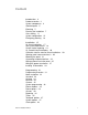
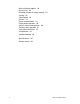
Content Introduction 3 Product overview 3 System components 4 Standard panel 5 Planning 7 Planning the installation 7 Cross-zoning 11 System configuration 12 Emergency planning 16 Installation 17 UL listed installations 17 SIA system requirements 18 Central station reporting 19 UL Canada listed installations 20 California state fire marshal listed installations Opening panel cover and chassis 20 Mounting the panel 21 Connecting hardwired devices 22 Wiring a phone line to the panel 25 Wiring the power trans
Audio verification options 50 System tests 54 Resetting memory to factory defaults 54 Testing 56 Control panel 56 Sensors 57 Phone communication 59 Offsite phone operation 60 Central station communication 60 Two-way voice operation 61 Voice event notification 62 X10 operation 62 Troubleshooting 64 Specifications 65 Sensor names 66 ii Simon XT Installation Manual
Introduction This chapter provides an overview of the system and an outline of the steps you need to perform before you begin installing and configuring your security system. Product overview This security system can be used as a fire warning system, an intrusion alarm system, an emergency notification system, or any combination of the three.
You can program the panel onsite from the keypad or remotely using Enterprise Downloader software. See “Programming” on page 31 for complete onsite programming instructions. System components The system can monitor up to 40 sensors and may use any of the devices listed in Table 1. Table 1: Supported devices Device Description Door/window sensor For intrusion protection, install door/window sensors on all ground-floor doors and windows.
Device Description Smoke sensor Smoke sensors provide fire protection by causing an alarm to sound throughout the house. You can add smoke sensors near sleeping areas and on every floor of the house. Avoid areas that could have some smoke or exhaust such as attics, kitchens, above fireplaces, dusty locations, garages, and areas with temperature extremes. In these areas, you may want to install rate-of-rise sensors to detect extreme temperature changes.
Hardware Capability Phone line connection Allows the panel to communicate with the central monitoring station and/or remote phone. Inspect the package and contents for visible damage. If any components are damaged or missing, do not use the unit; contact the supplier immediately. If you need to return the unit, you must ship it in the original box.
Planning This chapter provides information to help you plan your installation to reduce time and costs. Planning the installation This section describes system capabilities to help you get familiar with your system. The planning sheets contain tables that let you record the hardware and programming configuration of your system. Complete all of the information ahead of time to help prepare for system installation.
Device Recommended sensor group Outdoor motion sensor 25 (chime only) Entry/exit door 10 Interior door 14 Window sensor 13 Smoke sensor 26 Key fob 01, 03, 06, 07 ELM key fob 01, 03, 06, 07 Remote Handheld touchpad 01, 03, 06, 07 CO alarm 34 Freeze sensor 29 Water sensor 38 Personal help button 01, 03, 06, 07 Supervised Siren type Restoral Name/application Delay Type Table 4: Sensor group characteristics Active in arming levels 00 Fixed panic: 24-hour audible fixed emergenc
Supervised Restoral Active in arming levels 10 Entry/exit delay: A delay that requires a standard delay time. Chime. Intrusion S Y Y 24 13 Instant perimeter: Exterior doors and windows. Chime. Intrusion I Y Y 24 14 Instant interior: Interior door. Intrusion F Y Y 234 15 Instant interior: Interior PIR motion sensor. Intrusion F Y Y 234 16 Instant interior: Interior door. Intrusion F Y Y 34 17 Instant interior: PIR motion sensor and sound sensor.
Supervised Restoral Active in arming levels 36 Special intrusion: Such as gun cabinets and wall safes. Reports as tamper if tripped. Intrusion I Y Y 1234 37 Light switch control: X10 modules turn either on or off when a door is opened. b Silent I N Y 01234 38 Auxiliary: Water sensor. Trouble beeps I Y Y 01234 39 Local instant interior: 24-hour local alarm zone protecting anything that opens and closes. No report. Intrusion I Y Y 1234 40 Local special chime.
Sensor # Device Sensor group Sensor name/location Notes 20 21 22 23 24 25 26 27 28 29 30 31 32 33 34 35 36 37 38 39 40 Cross-zoning Cross zoning (two-trip) refers to two different group 18 sensors that must be tripped within two minutes of each other to report an alarm to the central station. Figure 2 on page 12 shows the path of a person walking from the kitchen to the living room.
Figure 2: Cross-zone diagram Note: We do not recommend cross-zoning for exit/entry zones. Each zone can individually protect the intended area. System configuration Table 6 below is a worksheet for you to record the desired values for each programming option. For each option, the default value, effect of deletion (pressing DISARM while editing), range, and programming privilege are also listed.
Function Default Delete Range Access code User code 7 None None 3 to 6 digits D, I, M User code 8 None None 3 to 6 digits D, I, M Duress code None None 3 to 6 digits D, I, M Code length 4 4 3 to 6 D Account number 00000 00000 0 to FFFFFFFFFF D, I Downloader code 12345 12345 00000 to 99999 D Phone lock Off Off On/Off D Auto arm On Off On/Off D, I Exit extension On Off On/Off D, I Secure arming Off Off On/Off D, I No arm low battery Off Off On/Off D,
Function Default Delete Range Edit sensors Access code Installer settings D, I Reporting menu Report options Opening reports Off Off On/Off D, I Closing reports Off Off On/Off D, I Forced armed Off Off On/Off D, I AC power failure report Off Off 5 to 254 minutes, off D, I Low CPU battery report On Off On/Off D, I Sensor alarm restoral Off report Off 1 to 3, Off D, I 24-hour sensor tamper report Off Off On/Off D, I Supervisory/ tamper report Off Off On/Off D, I
Function Default Delete Range Access code Alarm cancel 6 minutes Off 6 to 255 minutes, Off D, I RF timeout 12 hours 12 hours 2 to 36 hours D, I Fail to open time Off Off 12:00 midnight to 11:59 PM, Off D, I Fail to close time Off Off 12:00 midnight to 11:59 PM, Off D, I Siren timeout 5 minutes Off 2 to 254 minutes, Off D, I Arming LED shutdown Off Off On/Off D, I Unvacated premises On Off On/Off D, I Smoke supervision Off Off On/Off D, I Installer settings Touch
Function Default Delete Range Access code Alarm report verification Off Off On/Off D, I Audio mode Off Off 1, 2, or Off D, I Fire shutdown Off Off On/Off D, I Panic talk Off Off On/Off D, I Vox receiver gain 6 6 1 to 32 D, I Vox mic gain 24 24 1 to 64 D, I Vox mic gain range 64 64 1 to 64 D, I Manual mic gain 64 64 1 to 64 D, I Installer settings Audio verify menu System test menu Sensor test D, I, M Communication test D, I, M System download D, I, M Emer
Installation This section describes how to open the panel for mounting, mount the panel, connect sirens, connect hardwired contacts, and connect the AC power transformer. UL listed installations Some installations may require configurations dictated by city/state codes, insurance, or Underwriter’s Laboratories (UL). This section describes the various component and configuration listings. Basic system: • • • Control panel: backup battery 6 V 1.2 Ah (34-025) (Portalac model # PE6V1.
• • Hardwired siren supervision set to on Smoke supervision must be set to on UL 1023 & 985 24-hour backup: • For 24-hour backup, the total current draw for all connected devices is limited to 250 mA (during normal standby conditions) using a 1.2 AH battery. UL 1635 digital alarm communicator system: • Same as UL 1023 & 985, plus: The following settings are in addition to UL 1023 and 985 and are required only if the system is set up for central station reporting.
Function Default setting Required setting Call waiting Off On if reporting to central station and customer has call waiting service Exit extension On On Swinger shutdown On (one trip) On (one trip) Fire alarm verify Off On Duress/panic code Disabled Disabled Cross zone Disabled Disabled for zones with high probability of false alarms. Table 8 below describes nonprogrammable (hard-coded) system operation, as required to meet ANSI-SIA CP-01, and is provided only for your reference.
UL Canada listed installations This section describes the requirements for CUL (UL Canada) listed installations. Canadian standards CSA certified accessories Standard Class 2, 9 VAC, 3.34 A power transformer (UTC Fire & Security model 22-153-CN).
Figure 3: Opening the panel cover and chassis Mounting the panel To mount the panel on a wall, do the following: 1. Choose a panel location. 2. Run all necessary power, phone, siren, and hardwired contact wires to the desired panel location. Note: When choosing the AC outlet location for the AC power transformer, make sure the outlet is not controlled by a switch or that it is not part of a ground fault circuit interrupt (GFCI). 3.
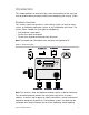
Figure 4: Panel mounting hole locations 5. Connect the chassis assembly to the mounted back piece and let it hang down. This makes the terminal strip accessible for wiring various hardwired components to the panel. 6. Feed wires through openings in the back piece to be ready to attach them to the screw terminals or the phone connectors. 7. Install all screws and tighten gently. Connecting hardwired devices The panel has seven screw terminals and two telephone connections (Figure 5 on page 23).
Figure 5: Simon XT terminal connections HW1 I/O, HW2 in, and HW1&2 DC out terminals The HW1 I/O terminal is dual purpose and can be used for either siren or hardwired contact connections. The HW2 in terminal is an input only. Interior sirens From the factory, the HW1 I/O input is set up for interior siren operation (status and alarm sounds). HW1&2 DC out provides the positive (+) voltage. Note: The total current available from the HW1&2 DC out terminal is 250 mA at up to 120°F (49°C).
Figure 6: Hardwired interior siren with supervision Hardwired contacts To set up HW1 I/O and/or HW2 in for hardwired contacts, make the required connections as described under below, then proceed to the Programming on page 33 to add (learn) them into panel memory. You can connect hardwired reed switches (normally closed loop only) to HW1 I/O (if not being used for a hardwired siren) and/or HW2 in. Note: Connect only normally closed (NC) reed switches to HW1 I/O and/or HW2 in.
Figure 7: Connecting normally closed hardwire reed switches Wiring a phone line to the panel You can connect a phone line to the panel for systems monitored by a central monitoring station or systems that notify users by a voice event notification. DSL (digital subscriber line) allows the use of multiple devices on a single phone line simultaneously. For DSL environments, connect the panel line-in jack to an available phone jack on the premises.
3. Disconnect the green and red premises phone jack wires from the Telco block D and splice them C to the four-conductor cable A black and white (or yellow) wires. Use weatherproof wire connectors for these splices. 4. Connect the four-conductor cable A green and red wires to the Telco block D TIP (+) and red to RING (–) posts. 5. Connect the phone cord E included with the panel to the RJ31X B and the panel LINE jack.
2. Connect the included phone cord to the panel LINE jack and the premises phone jack B. Note: If customers add phones or other phone devices to another phone jack, full line seizure no longer exists.
Figure 10: Transformer connections Note: Do not plug in the transformer at this time. Powering up the panel When applying power to the panel connect the battery first, then plug in the AC power transformer. This sequence prevents a battery fault condition. Note: Maximum battery charge current is 60 mA. It may take up to 24 hours for a new battery to fully charge. Installing the backup battery To install the backup battery (6 VDC, 1.2 Ah), do the following: 1.
Figure 11: Installing the panel backup battery Applying AC power Make sure the outlet is not controlled by a switch or that it is not part of a ground fault circuit interrupt (GFCI). 1. Remove the center screw from the outlet cover plate and hold the cover plate in place. WARNING: Use extreme caution when securing the transformer to a metal outlet cover. You could receive a serious shock if a metal outlet cover drops down onto the prongs of the plug. 2.
Caution: Do not plug appliances or lamps with 300-watt or larger bulbs into lamp modules. To install universal modules, do the following: 1. Set the unit code dial to a unit number different from all other X10 modules (between 1 and 8). 2. Set the housecode for the installation. 3. Set the module switches to momentary and relay only. 4. Connect the module terminals to the desired device terminals. 5. Plug the universal module into a wall outlet.
Programming This chapter provides steps on how to program your unit. Programming overview The control panel Figure 12 below provides the main processing unit for all system functions. The programming of system options and features is menudriven. All installer options are set in the System Programming menu, except for setting the system time. Table 9 below explains the panel keys and features shown in Figure 12 below.
Control Description Disarm Press to turn off intrusion/burglary protection for your system. Only intrusion/burglary sensors such as doors, windows, and motion sensors are disarmed. Environmental sensors, such as smoke and carbon monoxide, stay active at all times. Status Press to determine system status. Silent Press to silence exit beeps when arming. Bypass Press to bypass a sensor.
Menu navigation Each menu contains a list of options and/or submenus. Press the scroll up/down buttons to navigate up and down the list of options and submenus in that menu. Pressing the Enter key after navigating to an option selects that option for editing and flashes the current value. Pressing the Enter key after navigating to a submenu enters that submenu, making a new list of options accessible. Pressing STATUS exits a menu and goes to the next higher level.
System Tests Sensor Test Communication Test Initiate Download Call Revision Contrast Set clock If the panel loses both AC and battery power, then upon power restoral the system time will reset to midnight and blink, indicating it has not been set correctly. You can set the system time to display in either 12-hour or 24-hour format.
MM = month DD = day To set the date: 1. Scroll until the display shows Set Date, and then press OK. The display shows Enter Code. 2. Enter your code with the numeric keys, and then press OK. The display shows the date. 3. Press OK. The display flashes the year. 4. Scroll to set the year, and then press OK to accept the setting. The display flashes the month. 5. Scroll to set the month, and then press OK to accept the setting. The display flashes the day. 6.
System programming To enter system programming: 1. Scroll until the display shows System Programming, and then press OK. The system prompts for an access code. 2. Enter the access code from the codes listed in Table 11 below. The system displays each entered access code digit as an asterisk. 3. Press OK. The panel is now in program mode. Note: Do not remove the panel power while in program mode.
Function Default Description Duress code Blank Use the duress code in place of the master or user code to cause a silent alarm. Code length Four digits Codes can be three to six digits long. Security Function Default Description Account number 00000 Lets you program up to a 10-character alphanumeric account number or delete an existing account number by pressing Disarm. You can enter numerical digits sequentially.
Function Default Description Exit extend On Determines whether the panel restarts the exit delay time if you enter the armed premises during the initial exit delay period (on), or not (off). Turning on this feature allows you to reenter during the exit delay period, without disarming and then rearming the system. Turning off this feature requires you to disarm and rearm the system. Auto arm must be on for this option to work.
Phone options Table 13: Phone Options menu Function Default Description Man phone test On Determines whether you can perform a manual communication test to verify communication to a central station/voice dial (on), or not (off). If you have all four phone numbers programmed, it should send a test report to all four before showing that the test is okay.
Function Default Description Dial delay 30 seconds Determines whether the panel delays dialing programmed phone numbers before sending report (on). If opening (disarming) reports is on, the panel does not delay dialing if the system is disarmed before the delay time expires. The panel dials immediately for both the alarm and opening report. Regardless of this option setting, the panel always dials immediately for fire alarms, AC power failure, and low battery reports.
2. Enter the dealer or installer code and then press OK. The display shows Access Codes. 3. Scroll until the display shows Sensors, and then press OK. The displays shows Learn Sensor. 4. Press OK. The display shows Trip Sensor ##, with the number signs flashing. If you wish to use a sensor number other than the next one available, use the number keys to enter a two-digit sensor number immediately. 5. Press the sensor program button or release the sensor tamper switch.
Table 15: Device programming Device To program Door/window sensor Press the button on the top of the sensor (cover removed) or trip the tamper. Motion sensor Press the button on the back of the sensor (mounting plate removed) or trip the tamper. Smoke detector Trip the tamper, press the test button, remove the detector from its base, or put the smoke detector into alarm. Hardwired sensor Separate the sensor from its magnet.
Table 16: Reporting menu Function Default Description Opening reports Off Determines whether the panel sends opening reports to a central station whenever the system is disarmed (on), or not (off). The User number will be reported as zone number. Key fobs learned into zones 1 to 40 will report as that zone.
Function Default Supervisory tamper Off Description Determines whether the panel sends supervisory reports to a central station as a tamper (on), or a supervisory (off). This option is typically used only in Europe where a supervisory condition is required to report as a tamper. No usage Off Determines whether the panel sends a No Usage report to the central station if the user has not operated the system before the programmed time expires (on), or not (off).
Nonalarms include: Latchkey, No Activity, Openings, Closings, Fail-to-Open, Failto-Close, Force Armed, AC Power Failure, CPU Low Battery, and Trouble Restoral. Timers Table 18 below describes the Timers menu. Table 18: Timers menu Function Default Description Latchkey time Off Determines whether the panel reports a latchkey alarm if the system is not disarmed at a preset time between midnight and 11:59 p.m. (on). If the latchkey feature is disabled (off), the panel will not report a latchkey alarm.
Function Default Description Alarm cancel 006 minutes Sets the time frame that determines whether the panel reports an alarm cancel message to the central station. If the system is disarmed from an alarm state within the programmed time, the panel sends an alarm cancel message to the central station. An alarm cancel message is not reported if the system is disarmed after the programmed time expires. The time can be set from 006 to 255 minutes.
Touchpad options Table 19 below describes the Touchpad Options menu. Table 19: Touchpad Options menu Function Default Description Keyfob no delay Off Determines whether a key fob arms the system with no delay (on), or not (off). When this feature is on, you must disarm the system before entering the premises, since it is disabling the entry delay. If the remote touchpad arming option is on, key fobs cannot disarm the system and will cause an alarm upon entering.
Function Default Description HW1 function 1 Determines how the HW1 I/O output will function: Off = no output 1 = interior siren output 2 = output activated when armed 3 = output activated when disarmed 4 = fail to communicate output, activates when fail to communicate condition occurs (the fail to communicate option must be on) 5 = alarm output activated when panel is in alarm 24-hour clock Off Determines whether the panel uses a 24-hour clock (on), or a 12-hour clock (off).
Function Default Description Voice chime Off Determines whether the panel announces the sensor name. 1 = sensor name 2 = loud ding-dong bell 3 = soft ding-dong bell Off = no sound Status beeps vol 7 Determines the panel piezo volume level for status sounds such as arming, trouble, and status beeps. Volume range is 1 (lowest) to 10 (highest). HW siren sup Off Determines whether the panel monitors hardwired sirens for open conditions (on), or not (off).
Activity Piezo beep response Arm doors/windows and motion sensors Exit delay. Four beeps sound every 5 seconds and four times per second during the last 10 seconds. Silent exit. Four beeps sound at the beginning of the exit delay and four more sound just before the exit delay expires. Entry delay. Four beeps sound every 5 seconds and four times per second during the last 10 seconds. Disarm One beep. Chime Two beeps (when programmed). Special chime Three beeps (when programmed).
Function Default Description VOX mic gain 24 Determines the mic gain (sensitivity) that triggers the voiceactivated switching (VOX). Room size, acoustics, and furnishings where the panel is located will influence the setting. Gain range is 01 (lowest) to 64 (highest). VOX mic gain rng 64 Determines the gain range for voice-activated switching (VOX). Range is 01 (lowest) to 64 (highest). For best results, this option should be set equal to or greater than VOX mic gain.
3. Enter your access code and press Enter. The panel displays Access codes. 4. Press the scroll buttons until the panel displays Light control. 5. Press Enter. The panel displays Set entry lights. 6. Press Enter. The panel displays Entry light unit 1 on/off. 7. Press the scroll buttons until the unit number you want to program displays. 8. Press Enter. The panel displays Off, which will be flashing. 9. Press the scroll buttons until the panel displays On, then press Enter. 10.
7. Press the scroll buttons until the panel displays Light schedules. 8. Press Enter. The panel displays Light schedule 1 <--:-- - --:-->. 9. Press the scroll buttons until the panel displays the unit number you want to program. 10. Press Enter. The HH of the start time will flash. 11. Press the scroll buttons to set the hours. 12. Press Enter. The MM of the start time will flash. 13. Press the scroll buttons to set the minutes. 14. Press Enter. The AM/PM of the start time will flash. 15.
Function Light schedules Light schedule, Default Description Off In this menu, a light schedule can be programmed for each X-10 module with unit number from 1 to 8.
Program the panel in this order: 1. Set the panel clock. 2. Add (learn) sensors. 3. Change options as needed. Note: If phone lock is on, phone numbers 1 and 2, downloader phone number, account number, phone lock, downloader code, phone report modes 1 to 4, access code length, and call waiting and dealer code will not reset to their defaults.
Testing This section describes how to perform various test procedures. You should test the system after installing, after servicing, and after adding or removing devices from the system. Control panel Test the panel by pressing the buttons as described in Table 26 below. Table 27 below provides a list of the arming levels. Note: An access code is required when arming if the secure arming option is on.
Arming level Description Indication 1 Disarm the system. One beep indicates the system is disarmed. The panel displays and speaks Disarmed. The Disarm button lights. 2 Arm doors and windows. Two beeps verify that door/window sensors are armed. The panel displays DOORS+WINDOWS and speaks Doors and Windows On. The Doors+Windows button lights. 3 Arm motion sensors. Three beeps verify that motion sensors are armed. The panel displays Motions and speaks Motions On. The Motions button lights.
If you press Status and the panel has not heard from all sensors, the displays shows SN Test Fail or Aborted. Table 28: Sensor tripping instructions Sensor Do this Door/window Open the secured door or window. Freeze Remove the sensor cover. Apply ice in a plastic bag to the sensor (for 10 to 15 minutes). Do not allow the sensor to get wet. Water Press a wet rag or wet finger over both of the round, goldplated terminals on the underside of the sensor. Carbon monoxide alarm Unplug the CO alarm.
Sensor test failure If sirens do not beep when a sensor is tripped, use an RF Sniffer (60-401) test tool to verify that the sensor is transmitting. Constant beeps from the RF Sniffer indicate a faulty sensor. Replace the sensor. If possible, locate sensors within 100 ft. (30 m) of the panel. While a sensor may have a range of 500 ft. (152 m) or more out in the open, the environment at the installation site can have a significant effect on transmitter range.
If the test is unsuccessful, the Status button lights and the display shows Comm Failure within 10 minutes. If the test is unsuccessful: 1. Check that the panel is connected to the phone jack. 2. Check the phone number programmed into the panel. 3. Perform the communication test again. 4. If the communication test fails again, check the phone connection wiring. Offsite phone operation Test the system from a remote phone by calling the panel and using the commands in Table 30 below.
To test communication with the central station: 1. Call the central station and tell the operator that you will be testing the system. 2. Arm the system. 3. Test each of the wireless panic buttons and trip at least one sensor of each type (fire, intrusion, etc.) to verify that the appropriate alarms are working correctly. 4. When you finish testing the system, call the central station to verify that the alarms were received.
Table 32: Audio verification set Phone button Function 0 or 1 Speak 2 VOX operation 3 or 6 Listen 7 Extend session for 90 more seconds 88 Terminates session with call back (the panel answers on the first ring if called within 5 minutes) 99 Terminates session with no call back Voice event notification Testing this feature requires two people; one at the alarm site and the other at the location the panel is programmed to call. To test voice event notification: 1.
• • Keyfob: Press the Light button repeatedly to turn all lights on and off. The panel responds with Lights on/off. Remote handheld touchpad: Press the Lights on button and the unit number of the lamp module using the numeric buttons to test individual lamp modules 1 through 8. The panel responds with Light # on/off. Pressing the Lights on or Lights off button twice turns all the lights on or off.
Troubleshooting This chapter provides information to help you troubleshoot problems, perform simple preventive maintenance procedures, and contact technical support in case you need assistance with your UTC Fire & Security equipment. System status To clear Status (alarm memory), from a disarmed state press Status, listen to the status message, and then press Disarm.
• • • Make sure the battery is good and installed correctly. Check for interference from metal objects. Move or rotate the sensor. Move the sensor to a new location. If a door or window is closed, but the panel announces it is open: • • Be certain the arrow on the magnet and the guide line on the transmitter are aligned and within ¼ inch of each other. The sensor tamper switch may be open (cover off).
Sensor names The following tables provide alphabetical and numerically sequential lists of the sensor name segments.
027 Den window 028 Garage 029 Special chime 030 Basement 031 Basement window 032 Upstairs 033 Upstairs window 034 Downstairs 035 Downstairs window 036 Hallway 037 Medicine cabinet 038 Closet 039 Attic 040 System panic 041 Module 042 Phone module 043 A 044 B 045 C 046 D 047 E 048 F 049 G 050 H 051 I 052 J 053 K 054 L 055 M 056 N 057 O 058 P 059 Q 060 R 061 S 062 T 063 U 064 V 065 W 066 X 067 Y 068 Z 069 0 070 1 071 2 07
68 Simon XT Installation Manual