
Installation Instructions
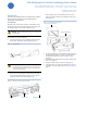
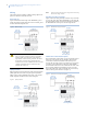
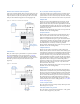
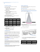
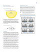
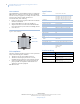
Table Of Contents
- Introduction
- Installation
- Wiring
- DIP switch options
- Initial power up
- Pattern adjustment
- Operation
- FCC compliance
- Specifications
- Product ordering

RCR-REX Request-to-Exit Dual Technology Motion Sensor
Installation Instructions
4
DIP switch options
The factory default (D) setting is on for all switches.
S2-1 (sounder enable)
On. Sounder is enabled for all modes (D).
Off. Sounder is completely disabled.
S2-2 (LED control)
On. LED is enabled (D).
Off. LED is disabled except during warm-up.
S2-3 (timer reset mode)
On. Relay timer does not reset with motion (D).
Off. Relay timer resets with motion.
S2-4, S2-5, S2-6 (relay time)
These switches determine how long the lock relay stays ener-
gized when motion is detected (Table 1).
S2-7 (door monitor mode)
On. Monitor the door switch (D).
Off. Do not monitor the door switch.
S2-8 (relay mode)
On. Fail safe mode (D) is enabled.
Off. Fail secure mode is enabled.
Initial power up
After mounting and wiring the sensor, apply AC or DC power to
the input power terminals (V+ and V-). Allow at least 2 minutes
following power up for the sensor to stabilize before conducting
any tests.
To walk test the detection pattern, approach the door from all
directions and watch the walk test LED for detection. See
Pattern adjustment if changes are required in the detection area.
Reassemble the sensor and completely walk test again following
any lens adjustment.
To select the appropriate relay time, set the DIP switches as
shown in DIP switch options on page 4.
LED indicator
The LED turns red for the duration of the lock relay time when
motion is detected and flashes twice per second during the 20-
second warm-up period. The LED turns yellow when the radar
detects motion. The LED turns green when the passive infrared
(PIR) detects motion.
Internal sounder
A continuous tone will sound 15 seconds prior to the end of the
relay timer period. A beeping tone will sound at the end of the
external input (X) signal if the door is open.
Pattern adjustment
The RCR-REX has both PIR and radar detection patterns that
may be adjusted independently.
PIR detection pattern
Figure 10 shows the passive infrared (PIR) detection pattern.
Figure 10. PIR detection pattern
To adjust the PIR detection pattern toward or away from the door
opening, do the following:
1. Open the sensor cover (Figure 1 on page 1) and loosen the
PCB axle screw (Figure 11).
Figure 11. PIR pattern adjustment
2. Rotate the PCB to the desired position and tighten the PCB
axle screw. Table gives the suggested angle for a given
mounting height.
3. Close the cover.
4. Test to be sure undesired sources of motion will not be detected.
Table 1. Relay time settings
Relay time S2-4 S2-5 S2-6
1/2 seconds (D) On On On
1 second On On Off
2 seconds On Off On
4 seconds On Off Off
8 seconds Off On On
16 seconds Off On Off
32 seconds Off Off On
64 seconds Off Off Off
Table 2. Suggested angles
Mounting height Wall angle Ceiling angle
7 ft. (2.1 m) -10° +10°
10 ft. (3.0 m) -20° +20°
15 ft. (4.6 m) -30° +30°
Door
Floor
RCR-REX sensor
Axle locking screw
Rotate PCB