
Installation Manual


Page 4
Quik Bridge ® Two-Channel Receiver
Overview of Receiver Operation
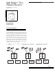
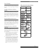
Figure 1. Parts of the Receiver
Programming Button
Use the programming button (see Figu re1) when
doing the following procedures:
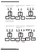
■ Deleting All Wireless Devices (see pa ge8)
■ Adding Wireless Devices (see pa ge8)
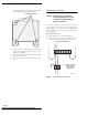
Zone Outputs
The receiver has eight terminals. Terminals 1 and 2 are
for power, 3–5 are for wiring zone 1, and 6–8 are for
wiring zone 2. Each zone can be configured to be nor-
mally closed (N/C) or normally open (N/O) (see
“Connecting the Receiver to a Control Panel” on
page 10).
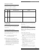
LED Indicator
The receiver has one LED. Table 1 lists the possible
states of the LED and what they mean.
Tools and Acces sories Needed
Included with Receiver
■ Four 1½'' screws
■ Wall anchors
Not Included with Receiver
■ Drill with assorted bits
■ EOL resistors (usually supplied with the panel)
■ Phillips screwdriver
■ Vo lt me t er
■ Wire stripper
9217G03B.DSF
LED INDICATOR
PROGRAMMING
BUTTON
TERMINAL STRIP
ZONE 2 N/O
ZONE 2 COMMON
ZONE 2 N/C
ZONE 1 N/O
ZONE 1 COMMON
ZONE 1 N/C
+11–15 VDC
GROUND
Table 1. What the states of the LED mean
Power LED Means
On and flickering
irregularly
Receiver has power and is func-
tioning normally.
Off Receiver has no power.
Flashing regu-
larly
Receiver is ready to learn a wire-
less device.