
Installation Manual


Page 10
Quik Bridge ® Two-Channel Receiver
double-clicks indicates the number of wireless
devices now added to the receiver.
5) To add another wireless device into zone 1, go
back to step 1 .
6) If necessary, complete the installation of the
device by adding it to the control panel (see the
panel installation instructions).
To add a wireless device to zone 2:
1) Press and hold the programming button. In about
three seconds you will hear and feel a “double-
click” from the receiver. Continue holding the
programming button until you hear a second
double-click from the receiver (3 s econds), then
release the programming button.
2) Wait three seconds. The LED will begin flashing,
indicating the receiver is ready to learn a new
wireless device.
3) Trip the device while holding it at arms length
from the receiver:
For sensors with tamper switches, activate the
tamper switch by removing the cover
For sensors without tamper switches, put the sensor
in alarm.
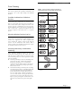
For Keyc ha in Touchpad s, press the desired pair of
buttons (see Tabl e3).
4) After about three seconds, the receiver will dou-
ble-click from one to four times. The number of
double-clicks indicates the number of wireless
devices now added to the receiver.
5) To add another wireless device into zon e2, go
back to step 1 .
6) If necessary, complete the installation of the
device by adding it to the control panel (see the
panel installation instructions).
Transmitting Key Codes
Before you can add an encrypted touchpad to a
receiver zone, you must use the following procedure
to transmit the enrypted key code for that touchpad
into the receiver memory.
1) Use steps 1-3 of the “Adding Wireless Devices”
procedure to prepare the receiver
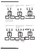
2) Press and release the unlock button twice, then
press and hold. The touchpad LED will begin a
slow, steady series of flashes. Continue holding
until the touchpad LED flashes three times, then
release.
3) Press and release the unlock button once, then
press and hold until the touchpad LED flashes
twice, then release.
4) Press and hold the unlock button until the touch-
pad LED flashes once. You will hear a double
click from the receiver, which indicates that the
receiver has successfully “learned” the key code.
Using X-10 Devices to Control
Light
By using an X-10 Powerflash Interface Module (13-
058) and X-10 Lamp Modules (13-204), you can use the
Lock and Unlock buttons on a Two- or Four-Button
Keychain Touchpad to turn lights on and of .
Setting up Light Control
To set up light control:
1) Program button mode A (for zon e1) or D(for
zone 2) into the receiver (see Tabl e3 for details).
2) Set the UNIT CODE and HOUSE CODE dials on
the Powerflash Interface Module to match those
on the Lamp Module(s).
3) Set the Powerflash Interface Module INPUT
switch to B and the MODE switch to 3.
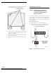
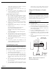
4) Using Figure 6 as a guide, connect the Powerflash
Interface Module to the appropriate receiver zone
output.
5) Plug in the Powerflash Interface Module and all
Lamp Modules.
Figure 5. Wiring a receiver zone output to the
Powerflash Interface Module
9217G25B.DSF
5
12
ZONE 1 N/O
Z
ONE 1 COMMON
ZONE 1 N/C
+11–15 VDC
GROUND
RECEIVER ZONE
OUTPUT TERMINALS
ZONE 2
POWERFLASH
INTERFACE
MODULE
34
876