NX-6V2 Control Panel Installation Manual P/N I-NX6V2-IM • REV C • ISS NOV12
Copyright © 2012 UTC Fire & Security Americas Corporation, Inc. Interlogix is part of UTC Climate Controls & Security, a unit of United Technologies Corporation. All rights reserved. This document may not be copied in w hole or in part or otherw ise reproduced without prior w ritten consent from UTC Fire & Security, Inc., except w here specifically permitted under US and international copyright law . Disclaim er The information in this document is subject to change w ithout notice.
Content Important information ii Chapter 1 Introduction 1 Product overview 2 Board installation 3 Wiring 3 Module list 6 Chapter 2 Programming 7 LED keypad programming 9 Control panel programming 12 Programming locations 17 Chapter 3 Troubleshooting 49 General diagnosis 50 Trouble conditions 50 Voltage tables 53 Specifications 54 Appendix A Reporting codes 55 Reporting fixed codes in Contact ID and SIA 56 Reporting zone codes in Contact ID and SIA 58 Reporting Ademco Contact ID transmissions 59 Device numbe
Important information This is the NX-6V2 Control Panel Installation Manual. This document includes an overview of the product and detailed instructions explaining how to install the NX6V2 board inside the enclosure and how to program the control panel. To use this document effectively, you should have the following minimum qualifications: • • ii A basic knowledge of electrical wiring and low-voltage electrical connections A basic knowledge of control panels.
Chapter 1 Introduction Summary This chapter provides an overview of your NX-6V2 Control Panel, including basic installation and terminal connections.
Chapter 1: Reporting codes Product overview The NX-6V2 Control Panel is a residential security and alarm system and provides the following features: • Sophisticated software allowing up to 40 users to interface with up to 16 zones and two partitions. • Integrated fire and input/output modules. • Fast SIA and Contact ID formats. • System expansion with up to 16 keypads and three modules. Keypads can include NX-148E-RF keypads that have built-in wireless receivers.
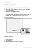
Chapter 1: Reporting codes Board installation Inside the metal enclosure, there are slots for board insertions. These allow the PC board to be positioned vertically (Figure 2 below). When you slide the board between the grooves of the slots, make sure the terminal strip is toward the front opening (toward you) to allow for the wire connections. Figure 2: Board installation Wiring Table 1 below lists wire lengths for one keypad at the end of the wire.
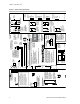
RED Aux. Outs 1 - 3Current limited to 250 microamps ve & when output is positi 50 mA when output is negative. Aux. Out 4 (as Smo ke +) Current limitedto 250 mA when output is positi ve and 250 microamps when output is neg ative. Aux 4 defaultsto SMOKE+ but can bereconfiguredto be used asZone 7for 2-wire smoke loop.Connect 680 ohm resistor betweenAux 4 &COM. ProgramLOC37, SEG 6,OPT 1. IF BOXTAMPERIS ENABLED IN LOC 37, CONNECT A NORMAL LY CLOSED SWITCHTOTHESE PINS . RGENCY BATTERYCAPACITY FOREME .
Chapter 1: Reporting codes Terminal descriptions Table 2 below describes the terminals shown in the wiring diagram. Table 2: NX-6V2 terminals Terminal Description R1 House telephone ring (gray wire on the standard RJ-31X card). R Telephone ring (red wire on the standard RJ-31X cord). T Telephone tip (green wire on the standard RJ-31X cord). T1 House telephone tip (brown wire on the standard RJ-31X cord). EARTH Earth ground. Connect to a cold water pipe or a 6 to 10 ft. driven rod. AC AC input.
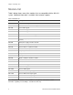
Chapter 1: Reporting codes Module list Table 3 below shows some of the modules that are compatible with the NX-6V2 system. Additional information is available from customer support. Table 3: Module list Part number Description NX-6V2 NX-6V2 control only. NX-6V2-KIT NX-6V2 control, NX-108E LED keypad, 16.5 V 40 VA transformer. NX-108E 8-zone LED keypad. NX-116E 16-zone LED keypad. NX-124E 24-zone LED keypad. NX-148E Alphanumeric 48-zone LCD keypad.
Chapter 2 Programming Summary This chapter provides basic programming instructions and a description of the programming locations.
Chapter 2: Reporting codes Location 44 - Duress code 36 Locations 45 to 50 - Auxiliary outputs programming 36 Location 51 - Autotest control 38 Locations 52 to 55 - Times and days 39 Locations 56 to 83 - 4+2 format communicator codes 40 Location 84 - Daylight saving time 43 Locations 88 to 91 - Partition account codes and features.
Chapter 2: Reporting codes LED keypad programming This section describes how to program the address of each LED keypad, as well as the options that are available. The keypad must be addressed for control panel supervision of that keypad. Programming defaults include: • • • • Four-digit master code: 1, 2, 3, 4. Six-digit master code: 1, 2, 3, 4, 5, 6. Four-digit go to program code: 9, 7, 1, 3. Six-digit go to program code: 9, 7, 1, 3, 0, 0. To assign the keypad’s LEDs to start at a zone other than one: 1.
Chapter 2: Reporting codes LED 8 Keypad feature enabled Enable multiple partition viewing. Enable temporary viewing of all partitions by pressing *, 1, partition number. Keypad number and partition To set the keypad number and partition: 1. Enter *, 9, 4, program code. The Service LED and the Instant LED will flash. 2. Enter the keypad number (1 to 8). 3. Press *. The Instant LED will illuminate steady and the Service LED will remain flashing. 4. Enter the partition number (1 or 2) for the keypad.
Chapter 2: Reporting codes System clock To set the system clock: 1. Enter *, 9, 7, master code. The Service LED begins flashing. 2. Enter the clock time (military time). Hour: 00 through 23, where 00 is midnight, 01 is 1:00 a.m., 23 is 11:00 p.m. Minutes: 00 to 59. For example, 3.25 a.m. = 0, 3, 2, 5; and 5:00 p.m. = 1, 7, 0, 0. User codes To change the user codes: 1. Enter *, 5, master code. The Ready LED begins flashing. 2. Enter the two-digit user number (for example, 03 for user 3).
Chapter 2: Reporting codes assigned authority levels to all user numbers, or you can press # to exit assigning authority level programming.
Chapter 2: Reporting codes To enter program mode: 1. Press *, 8. The five function LEDs (Stay, Chime, Exit, Bypass, and Cancel) begin flashing. 2. Enter the go to program code (default 9, 7, 1, 3). If the go to program code entry is valid, the Service LED flashes, and the five function LEDs illuminate. You are now in program mode and can select the module to program.
Chapter 2: Reporting codes You are now ready to enter another programming location. If you attempt to program and invalid entry for a particular segment, the keypad beeps three times indicating an error and remains in that segment awaiting a valid entry. To exit program mode: 1. When you have completed all programming, press Exit to leave the selected module. 2. If there is another module to be programmed, select it by entering its address, followed by #.
Chapter 2: Reporting codes Feature selection data Feature selection data displays the current condition (on or off) for eight features associated with the programming location and segment selected. Pressing a button on the touchpad (1 to 8) that corresponds to the feature number within a segment toggles (on/off) that feature. You can select numerous features within one segment. To enter feature selection data: 1. Press a numeric key from 1 to 8 to select the feature.
Chapter 2: Reporting codes a siren or bell is attached to the NX-6V2, it sounds for about 1 second. If the module is not detected, the Service LED illuminates. Note: User codes are not accepted during the enrolling process.
Chapter 2: Reporting codes Programming locations This section describes all the programming options for the control panel. Quick start programming For most routine installations, the quick start locations allow you to enable a majority of the options available with the NX-6V2 (when communicating in Contact ID or SIA formats).
Chapter 2: Reporting codes Caution: A call-waiting cancel on a non call-waiting line prevents successful connection to the central station. Location 1 Phone 1 account code Location 1 has six segments of numerical data. Use this location to program the account code sent when phone 1 is dialed. The default for each segment is 10. Program a 10 in the segment immediately after the last digit of the account code. If the account code is six digits long, program all six segments.
Chapter 2: Reporting codes Data Format Description 11 4+2 express Two-digit event code DTMF transmission. 12 4+2 fast Two-digit event code 1900 Hz transmit 1400 Hz handshake double round parity 20 pps. 13 Ademco contact ID DTMF (see “Reporting Ademco Contact ID transmissions” on page 59. 14 SIA Frequency shift keys (see “Reporting fixed codes in Contact ID and SIA” on page 56). 15 Custom format See “Location 18 - Custom communicator format” on page 24.
Chapter 2: Reporting codes Location 4 - Phone 1 events reported Location 4 has two segments of feature selection data. Use this location to select those events reported to phone 1. • If you do not want dual or split reporting, use Location 4 to select all events to phone 1. Location 5 should be left at the factory default of 0. • If you want dual or split reporting and the split is based on the event type (alarm, open/close, etc.), use Location 4 to select only those events that are reported to phone 1.
Chapter 2: Reporting codes • • Enter 11 for a *, and 12 for a #. Enter 14 to indicate the end of the phone number. Caution: A call-waiting cancel on a non call-waiting line prevents successful connection to the central station. Location 7 - Phone 2 account code Location 7 has six segments of numerical data. Use this location to program the account code sent when phone 2 is dialed. The default for each segment is 10. Program a 10 in the segment immediately after the last digit of the account code.
Chapter 2: Reporting codes • If you want dual or split reporting and the split is based on the event type (alarm, open/close, etc.), use only those events that are reported to phone 2. • If you don’t want events reported to phone 2, program 0 in Location 10. Segment 1 1. 2. 3. 4. 5. 6. 7. 8. Alarms and alarm restores. Opening and closings. Zone bypass and bypass restore. Zone trouble and trouble restores. Power fail, low battery, power restore, and low battery restore.
Chapter 2: Reporting codes Location 13 - Phone 3 account code Location 13 has six segments of numerical data. Use this location to program the account code sent when phone 3 is dialed. The default for each segment is 10. Program a 10 in the segment immediately after the last digit of the account code. If the account code is six digits long, program all six segments. If Location 6 Phone 2 is left unprogrammed, use account code 1 when phone 3 is dialed.
Chapter 2: Reporting codes Segment 1 1. 2. 3. 4. 5. 6. 7. 8. Alarms and alarm restores. Opening and closings. Zone bypass and bypass restore. Zone trouble and trouble restores. Power fail, low battery, power restore, and low battery restore. Bell cut, telephone line cut, bell cut restore, telephone line restore. Test reports. Start/end programming, download complete. Segment 2 1. 2. 3. 4. 5. 6. 7. 8. Zone and box tamper and tamper restore. Auxiliary power overcurrent and restore.
Chapter 2: Reporting codes Segment 1 1. 2. 3. 4. 5. 6. 7. 8. On for 1800 Hz transmit; off for 1900 Hz. On for 2300 Hz handshake; off for 1400 Hz. On for cksum parity; off for double round parity. On for two-digit event code; off for one-digit event code. Reserved. Reserved. On for 20 pps; off for 10 to 40 pps. On for 10 pps: off for 20 or 40 pps. Segment 2 1. 2. 3. 4. 5. 6. 7. 8. On for pager format (no handshake required). On for 1400/2300 handshake. Reserved. Reserved. On for contact ID. On for SIA.
Chapter 2: Reporting codes Segment 1 1. On enables two call answering machine defeat. 2. On enables tone sniff answering machine defeat. 3. On requires call back before download session. 4. Shutdown. (Can only be activated with the download software). 5. On locks all local programming. (Can only be activated with the download software.) 6. On locks programming of all locations associated with the communicator. (Can only be activated with the download software.) 7. On locks out download session.
Chapter 2: Reporting codes Locations 23 and 24 - Partition features Location 23 - Feature report selection/partition feature selection Location 23 has five segments of feature selection data. Use this location to enable certain features that are accessed or visible to the user from the system keypad. In addition, you can enable certain communicator reports in this location. Segment 1 1. 2. 3. 4. 5. 6. 7. 8. On enables quick arm. On enables re-exit. On enables automatic bypass.
Chapter 2: Reporting codes Location 24 - Entry/exit times Location 24 has six segments of numerical data. Use this location to program the entry/exit times (there are two separate entry/exit times). Segment 1 - Entry time 1. Entry time used when a delay 1 zone type initiates an entry delay. Default is 30, valid entries 30 to 255 seconds. Segment 2 - Exit time 1. Exit time used for all zones designated as delay 1. Default is 60, valid entries 45 to 255 seconds. Segment 3 - Entry time 2.
Chapter 2: Reporting codes Zone type Description 6. Instant Creates an instant alarm whenever it is tripped and the armed LED is on. 7. 24-hour silent Creates an instant silent alarm regardless of the armed state of the control panel. It does not display on the keypad. 8. Fire Illuminates the Fire LED and sounds the temporal siren each time the zone is shorted. The Fire LED flashes rapidly indicating a problem if the zone is open. 9. Entry/exit delay 2 A trip starts entry delay 2.
Chapter 2: Reporting codes Zone type Description 21. Gas detection Creates an instant alarm regardless of the armed state of the control panel. It displays on the keypad and activates the keypad sounder. 22. Low temperature detection Creates an instant silent alarm regardless of the armed state of the control panel. It displays on the keypad and activates the keypad sounder. 23. High temperature detection Creates an instant silent alarm regardless of the armed state of the control panel.
Chapter 2: Reporting codes Location 25 - Zones 1 to 8 zone type Location 25 has eight segments of numerical data. Use this location to program the zone type for zones 1 to 8. Use segment 1 for zone 1, segment 2 for zone 2, etc. The segment defaults are 3, 5, 6, 6, 6, 6, 6, 6. Location 26 - Zones 1 to 8 partition Location 26 has eight segments of feature selection data. Use this location to select the partitions (1 or 2) that zones 1 to 8 reside in.
Chapter 2: Reporting codes Location 37 - Siren and system supervision Location 37 has seven segments of feature selection data. Use this location to enable various system feature and reporting options. Segment 1 1. On if siren sounds for telephone line cut when armed. 2. On if siren sounds for telephone line cut when disarmed. 3. On if siren blast at arming. 4. On if siren blast at exit expiration. 5. On if siren blast at closing kissoff. 6. On if siren sounds during a cross zone verification time. 7.
Chapter 2: Reporting codes 5. 6. 7. 8. On will not allow zones that are force armed to report bypass. Reserved. On makes the clock use the internal crystal. On disables the temporal siren of fire. Segment 6 1. 2. 3. 4. 5. 6. 7. 8. On enables two-wire smoke. Reserved. On enables zone activity in hours (not days). On enables daylight saving time (DST). On enables DC only operation. On disables clean me report. On disables start/end walk test report. On enables auto LED extinguish.
Chapter 2: Reporting codes Segment 4 - Siren time in minutes, 1 to 254. Default is 8. Segment 5 - Telephone line cut delay in seconds, 0 to 255 (0 = no monitoring). Default is 0. Segment 6 - Cross zone time in minutes, 0 to 255 (0 = no cross zoning). Default is 5. Segment 7 - Chime time in 50 mS increments from 0 to 12 seconds. Default is 3. Segment 8 - Dial delay in seconds, 15 to 255 (0 = no abort delay). Default is 30.
Chapter 2: Reporting codes Location 41 - Special features Location 41 has one segment of feature selection data. Segment 1 1. On enables the six-digit code option. If enabled, all arm/disarm codes and the go to program code are six digits. The default user 1 code is 123456. Caution: If you enable this option verify that the go to program code is a six -digit code before exiting programming. 2.
Chapter 2: Reporting codes Note: All segment 2 features must be on for the go to program code to be used to change user codes. Location 44 - Duress code Location 44 has six segments of numerical data. Use this location to program the duress code. This location contains either four or six digits. If the six-digit code option is enabled, this code must contain six digits. If the six-digit option is not enabled, the last two digits are ignored. Each segment default is 15.
Chapter 2: Reporting codes Location 48 - Auxiliary output 2 event and times Location 48 has two segments of numerical data. Segment 1 - Use Table 8 below to select the event that activates auxiliary output 2. Default is 1 Segment 2 - Program the timing from 0 to 255 (minutes or seconds, depending on data programmed in Location 46, segment 1). Programming a 0 makes the output follow the event. Default is 10 (seconds).
Chapter 2: Reporting codes 16 = Autotest a 17 = Alarm memory 18 = Entry 19 = Exit 20 = Entry or exit 21 = Armed state (follows Armed LED) 22 = Disarmed state 23 = Ready 24 = Not ready 25 = Fire (follows Fire LED) 26 = Fire trouble 27 = Chime (chime must be on at keypad) 28 = Expander trouble a 29 = Dynamic battery test time 30 = Open period 31 = Closed period 32 = Listen in 33 = Line seizure 34 = Ground start (momentary at start of phone dial) 35 = Fail to communicate 36 = Telephone l
Chapter 2: Reporting codes Segment 1 Program the autotest interval. Enter 0 if the interval is in days (if the panel tests once daily, program one day rather than once every 24 hours) Enter 1 if the interval is in hours (default) Enter 2 if the interval is in days and suppresses the test if any report has been sent within the last autotest interval. Enter 3 if the interval is in hours and suppresses the test if any report has been sent within the last autotest interval.
Chapter 2: Reporting codes Segment 2 - Program the minutes after the hour of the closing/autoarm time. Default is 0 Location 54 - Days of week the system is open Location 54 has eight segments of feature selection data. Use this location to select which days of the week the system is open. On these days, arm only after close window codes are able to arm and disarm during open window. On days not selected here, arm only after close window codes are not disarmed (Locations 52 and 53).
Chapter 2: Reporting codes Location 56 Restore communicator code Program the event code for any zone restore for a 4+2 format. Location 57 Bypass communicator code Program the event code for a zone bypass for a 4+2 format. Location 58 Tamper communicator code Program the event code for a zone tamper for a 4+2 format. Location 59 Trouble communicator code Program the trouble communicator code for a 4+2 format.
Chapter 2: Reporting codes Location 72 Telephone line cut/restore communicator code Program the digits sent for a 4+2 format if telephone line cut reporting is enabled. Segments 1 and 2 = telephone line cut reporting Segments 3 and 4 = telephone line cut restore Location 73 Ground fault/restore communicator code Program the digits sent for a 4+2 format if ground fault reporting is enabled.
Chapter 2: Reporting codes Location 84 - Daylight saving time Location 84 has four segments of numerical data. Use this location to program when daylight saving time begins and ends. This will happen at 2:00 a.m. on the day programmed. The default is to begin daylight saving time on the second Sunday in March and end on the first Sunday in November. Segment 1 - Daylight saving time starting month (1 to 12). Default is 3. Segment 2 - Daylight saving time starting Sunday (1 to 4, first to fourth).
Chapter 2: Reporting codes Locations 92 to 109 - Reserved Locations 110 to 169 - Zone type characteristics Locations 110 to 169 are considered advanced programming and you should only change them with a thorough understanding of the operation of each bit. Table 9 on page 45 lists the attributes for each location. Caution: We recommend the installer bench test any custom zone types to ensure proper operation prior to making changes to a live system.
Chapter 2: Reporting codes Segment 3 1. On enables fast loop response (50 mS; off = 500 mS). 2. On enables double end of line tamper zone (mainly used to enable the tamper on wireless zone.) 3. On enables trouble reporting zone (day zones and fire zones). 4. On if zone type is cross zoned. 5. On enables dialer delay zone (see Location 40). 6. On if zone type is swinger shutdown (see Location 38). 7. On enables restore reporting. 8. On enables listen in (see Location 40). Segment 4 1.
Chapter 2: Reporting codes Location Zone type Description Default 125 8 Feature selection 1, 13, 378, 0, 0 126 9 Alarm code 7 127 9 Feature selection 6, 1245, 5678, 0, 0 128 10 Alarm code 2 129 10 Feature selection 24, 5, 78, 0,0 130 11 Alarm code 3 131 11 Feature selection 3, 0, 0, 0, 0 132 12 Alarm code 5 133 12 Feature selection 457, 125, 45678, 0, 0 134 13 Alarm code 4 135 13 Feature selection 0, 12458, 5678, 0, 0 136 14 Alarm code 7 137 14 Feature
Chapter 2: Reporting codes Location Zone type Description Default 158 25 Alarm code 14 159 25 Feature selection 248, 45, 0, 0, 0 160 26 Alarm code 5 161 26 Feature selection 467, 125, 5678, 0, 0 162 27 Alarm code 5 163 27 Feature selection 457, 1257, 5678, 0, 0 164 28 Alarm code 7 165 28 Feature selection 6, 12457, 5678, 0, 0 166 29 Alarm code 5 167 29 Feature selection 457, 125, 5678, 1, 0 168 30 Alarm code 7 169 30 Feature selection 5, 1245, 5678, 1, 0
Chapter 3 Troubleshooting Summary This chapter provides product specifications and information to help you troubleshoot the product.
Chapter 3: Reporting codes General diagnosis Trouble conditions are diagnosed by viewing the detailed information in the event log, using an LCD keypad. To view the event log: 1. Enter *, 9, 0 at the keypad. 2. Enter the master or installer code. The most recent event displays. 3. Press the down arrow to view backward in time, or the up arrow to move forward in time. Trouble conditions Look for the specific problem you are experiencing and follow the instructions to correct the problem.
Chapter 3: Reporting codes 3. The backup battery is shorted internally or is defective. Remove the battery. If the overcurrent disappears, install a new battery. The Fire LED is flashing. Press *, 7. This clears most trouble conditions and resets the smoke detectors. The control panel is in communication fail. Try to make the control panel complete a communication with the central station receiver. If communication between the control panel and the central station is not successful: 1.
Chapter 3: Reporting codes The siren does not work. The control panel has a built in siren driver. If the system uses self-contained sirens instead of speakers, go to Location 37, Segment 2, and turn on bit 1. This converts the driver output to voltage output. The interior zones are bypassing themselves. By default, auto bypass is on in Location 23, Segment 1, bit 3.
Chapter 3: Reporting codes Voltage tables The following tables show normal values for control panel voltages. if these values are incorrect, you may experience trouble or fault conditions. Table 10: Phone or power voltage values Phone or power voltage Value T to R and T1 to R1 50 VDC not communicating (on hook) T to R 7 VDC communicating (off hook) T1 to R1 0 VDC communicating (line seized) AC to AC 17.5 VAC Data to common 6 VDC nominal (1.5 to 10 V, fluctuates) Keypad positive to common 13.
Chapter 3: Reporting codes Specifications Operating power 16.5 VAC 40 or 50 VA transformer Auxiliary power With 25 VA transformer With 40 or 50 VA transformer With NX-320E power supply 12 VDC regulated 500 mA 12 VDC regulated 1 A 12 VDC regulated 2 A plus control panel power Loop resistance Standard loop Two-wire smokes 300 ohms max. 30 ohms max.
Appendix A Reporting codes Summary This appendix provides tables for various events and transmissions associated with the NV-8V2 control panel Content Reporting fixed codes in Contact ID and SIA 56 Reporting zone codes in Contact ID and SIA 58 Reporting Ademco Contact ID transmissions 59 Device numbers for reporting expander troubles 60 Zone ID or user ID hex digit for 4+2 formats 62 NX-6V2 Control Panel Installation Manual 55
Appendix A: Reporting codes Reporting fixed codes in Contact ID and SIA The NX-6V2 can report SIA level 1 transmissions to either or both phone numbers. Each report consists of an event code and a zone ID (the zone number that is in alarm) or user ID. Table 12 below shows the event code programmed in the zone type event code.
Appendix A: Reporting codes Contact ID event SIA Description 121 HA Keypad panic (silent) 137 TA Keypad tamper 309 YT Low battery (device number) 309 YR Low battery restore (device number) 601 RX Manual test 401 OP Open (user number) 401 CR Recent close (user number) 381 T 381 a b a a b a a c RF sensor lost (zone number) a R c RF sensor restore (zone number) 384 XR Sensor battery restore (zone number) 384 XT Sensor low battery (zone number) 321 YH Siren restore (
Appendix A: Reporting codes Reporting zone codes in Contact ID and SIA The NX-6V2 has the ability to report SIA transmissions to either or both phone numbers. Each report in SIA consists of an event code and a zone ID (the number of the zone that is in alarm) or user ID. table shows the event code, SIA code, and a description that is programmed in the zone type event code (Locations 110 to 169).
Appendix A: Reporting codes Reporting Ademco Contact ID transmissions The NX-6V2 has the ability to report Ademco Contact ID transmissions. Each report in Contact ID consists of an event code and a zone ID (the number of the zone that is in alarm). The event codes are described in the following table and are programmed in the zone type event code (Locations 110 to 169).
Appendix A: Reporting codes Device numbers for reporting expander troubles The following tables list the device names and numbers that report for trouble conditions.
Appendix A: Reporting codes Device Name Number 570E/580E Switch 3 on Device address 25 Switch 1 and 3 on Device address 26 Switch 2 and 3 on Device address 27 Switch 1, 2, and 3 on Device address 28 All switches off Device address 29 Switch 1 on Device address 30 Switch 2 on Device address 31 Table 16: Keypad numbers for reporting trouble conditions Keypad number Partition 1 2 1 192 193 2 200 201 3 208 209 4 216 217 5 224 225 6 232 233 7 240 241 8 248 249 NX-6V2
Appendix A: Reporting codes Zone ID or user ID hex digit for 4+2 formats Zone or user ID hex digits only apply to slow formats (Locations 56 to 83, lower digit). The digits programmed in these locations are sent as the upper hex digit in place of the alarm event code. The zone ID or user ID are always reported as the lower hex digits. The following table shows the hex digit for the zone/user IDs. For example, if the zone/user ID is 15, the 4+2 lower digit is F.
Appendix B Programming worksheet Summary This appendix provides a programming worksheet to check default settings and to record the settings for your installation.
Appendix B: Reporting codes Programming worksheet Use the following worksheet to check location defaults and record location settings. Locations with multiple segments will show defaults as multiple numbers separated by commas. Defaults are shown in bold. Table 18: Location defaults and settings Loc.
Appendix B: Reporting codes Loc.
Appendix B: Reporting codes Loc.
Appendix B: Reporting codes Loc.
Appendix B: Reporting codes Loc. Description Default Setting Segment 4 = Siren time (1 to 254).
Appendix B: Reporting codes Loc.
Appendix B: Reporting codes Loc. Description Default Segment 2 = Minutes.
Appendix B: Reporting codes Loc. Description Default 68 AC fail/restore communicator code 0, 0, 0, 0 69 Low battery/restore communicator code 0, 0, 0, 0 70 Power short/restore communicator code 0, 0, 0, 0 71 Bell tamper/restore communicator code 0, 0, 0, 0 72 Telephone line cut/restore com.
Appendix B: Reporting codes Loc.
Appendix B: Reporting codes Loc.
Appendix B: Reporting codes Loc.
Glossary Abort In enabled, the NX-6V2 waits the number of seconds programmed in Location 40 prior to sending an alarm. During this delay time, the Cancel LED flashes. To abort the report, type in a code and press the Cancel key. The LED extinguishes. If the report is not aborted within the allotted time, the LED extinguishes when the report is sent (a dialer delay must be enabled).
Glossary Automatic cancel/abort If enabled, the cancel and/or abort features are automatic (pressing the Cancel button is not required). The cancel and abort features in Locations 23 and 40 must be enabled to permit this auto feature to work. For proper operation of these features a dialer delay must be enabled.(Locations 40, 41, and 110 to 169) Autotest This feature causes the panel to call the central station to report a communicator test at a specified interval (Location 51).
Glossary Dual/split/multiple reports The NX-6V2 sends communication reports to three different phone numbers for dual, split, or multiple reports selectable by event or partition. (Locations 4, 10, 16, and 18) Duress code If programmed, the NX-6V2 sends a duress signal whenever the panel is armed or disarmed with this code. The user code is 254 if open/close reports are sent.
Glossary Fail to communicate The NX-6V2 illuminates the Service LED if a report fails to reach the central station. If enabled, when the next report is successfully communicated, a fail to communicate code is reported. (Location 37) Fire alarm verification When enabled, the NX-6V2 verifies a fire alarm by requiring more than one trip on a smoke detector within a specified time before creating an alarm (Location 40) Note: This feature is not approved for residential use in California.
Glossary Manual test If programmed, the NX-6V2 performs a bell and/or communicator test when *, 4, 4 is entered while the system is in the disarmed state. (Location 37) Night mode This mode applies to NX-1208E/1248E keypads. In this mode, the control panel bypasses all zones that have the entry guard feature enabled. (Locations 23 and 110 tp 169) Onboard zone disable For a completely wireless alarm system, the four zones on the NX-6V2 panel can be disabled.
Glossary Swinger shutdown This feature allows a zone or zones to be automatically bypassed after a specified number of alarms. When a zone is tripped, the alarm counter reflects 1 in memory. If a new (first) alarm is detected in a different zone, the counter remains at 1. If an alarm is detected on a previously tripped zone, the count increments to 2. The counter increments each time an alarm is detected on a zone with multiple trips.
Glossary Zone activity monitor This feature sends a report to the central station when a particular zone does not change conditions within a specified number of days programmed. (Locations 40 and 110 to 169) Zone bypassed sounder alert If enabled, the NX-6V2 beeps the keypad sounder upon arming if a zone is bypassed. (Location 23) Zone doubling Zone doubling can only be enabled when at least one other device is added to the basic system (consisting of the main control panel and one keypad).