
User Manual User guide
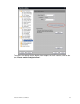
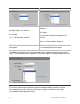
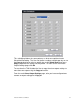
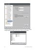
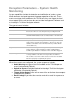
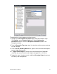
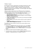
Table Of Contents
- Chapter 1 TVN 20 System Basics
- Chapter 2 TVN Advanced Topics
- HDD Configuration & Management
- Account Management (Users)
- Advanced Camera Settings
- Exception Parameters – System Health Monitoring
- Video Loss
- Remote Record & Video Download
- Additional Network Settings
- Remote Update
- Serial Port Settings – RS-232 & RS-485
- Log Files
- Appendix A Troubleshooting
- Appendix B TVN 20 Specifications
- Appendix C TVN 20 IP Camera Capacities
- Appendix D TVN 20 Supported IP Cameras
- Appendix E TVN 20 USB Archive Options
- Appendix F TruVision Device Finder
- Appendix GGlossary of Terms
- Appendix HWarranty and Support
86 TruVision NVR 20 User Manual
Analog Alarm Output options Digital Alarm Output options
Analog Outputs are shown as:
A = Analog
-> 1 = TVN 20 Alarm Input #1
Digital (IP Camera) Alarm Outputs are
shown as:
D = Digital
# = IP Camera Channel Number on the
TVN 20
- A-> 1 = Camera Alarm Output #1
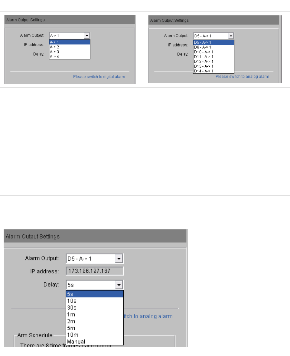
IP Address field will be Local for on the
unit outputs
IP Address field will show the IP address for
the selected digital alarm output
The Delay field identifies how long the output will be triggered following an activating
event. The available values, regardless if the alarm output is analog or digital area, are:
If the alarm output needs to follow a specific enabled/disabled schedule, from the
Arm Schedule area click settings to configure a specific schedule of up to eight
(8) enabled/disabled periods per day.