
User Manual User guide
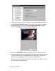
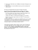
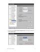
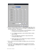
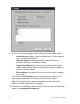
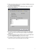
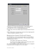
Table Of Contents
- Chapter 1 TVN 20 System Basics
- Chapter 2 TVN Advanced Topics
- HDD Configuration & Management
- Account Management (Users)
- Advanced Camera Settings
- Exception Parameters – System Health Monitoring
- Video Loss
- Remote Record & Video Download
- Additional Network Settings
- Remote Update
- Serial Port Settings – RS-232 & RS-485
- Log Files
- Appendix A Troubleshooting
- Appendix B TVN 20 Specifications
- Appendix C TVN 20 IP Camera Capacities
- Appendix D TVN 20 Supported IP Cameras
- Appendix E TVN 20 USB Archive Options
- Appendix F TruVision Device Finder
- Appendix GGlossary of Terms
- Appendix HWarranty and Support
78 TruVision NVR 20 User Manual
Please note that the text now shows “Please switch to analog alarm” and that
Alarm Input field shows an entry such as “D2 – A->1” which identifies that it is
a digital input (D) on IP Channel (2) and that the element is an alarm input (A)
and it is IP camera input (1).
2. From the Alarm Input field, select from the drop-down the IP camera input you
wish to configure.
3. Optionally, in the Alarm Name field you can name the alarm input. This name
is used for the logs and is captured by the Interlogix TruVision Navigator
software.
4. Select the Alarm Handle checkbox to enable the selected input for
configuring event response behaviors.
5. In the Arm Schedule area select Settings to configure the day or weekly
schedule for enabling the digital alarm input. By default when the digital input
is enabled (Alarm Handle Checked), the digital input is automatically enabled
24x7 (24 hours a day, every day).