
User Manual User guide
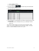
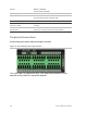
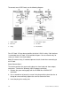
Table Of Contents
- Chapter 1 TVN 20 System Basics
- Chapter 2 TVN Advanced Topics
- HDD Configuration & Management
- Account Management (Users)
- Advanced Camera Settings
- Exception Parameters – System Health Monitoring
- Video Loss
- Remote Record & Video Download
- Additional Network Settings
- Remote Update
- Serial Port Settings – RS-232 & RS-485
- Log Files
- Appendix A Troubleshooting
- Appendix B TVN 20 Specifications
- Appendix C TVN 20 IP Camera Capacities
- Appendix D TVN 20 Supported IP Cameras
- Appendix E TVN 20 USB Archive Options
- Appendix F TruVision Device Finder
- Appendix GGlossary of Terms
- Appendix HWarranty and Support
124 TruVision NVR 20 User Manual
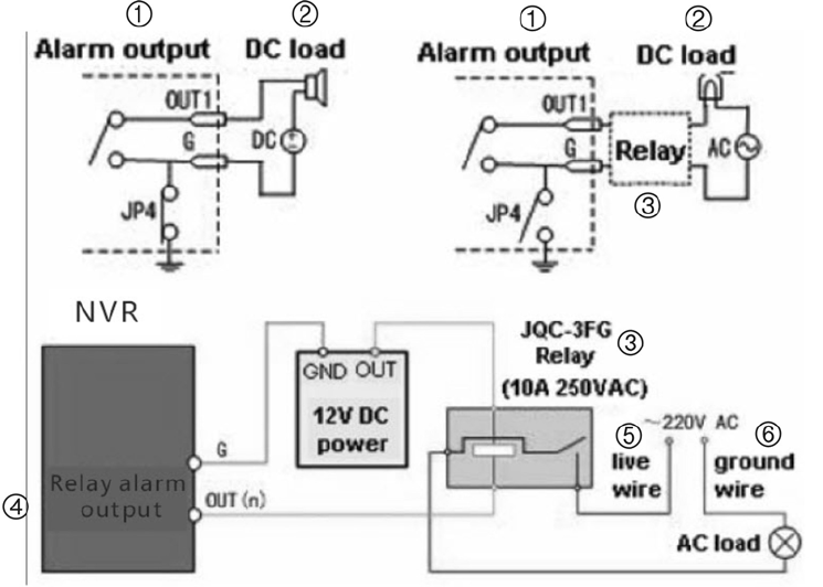
To connect to an AC/DC load, use the following diagram:
1. Alarm output
2. DC load
3. Relay
4. Relay alarm output
5. Live wire
6. Ground wire
For a DC load, JP4 can be used within the limit of 12V/1A safely. If the interface
is connected to an AC load, JP4 should be left open. Use an external relay for
safety (as shown in the figure above).
Note: An external relay is needed to prevent electric shock when connecting to
an AC load.
Alarm Connections:
The device provides the green mating plugs for alarm input and alarm output
connectors. Perform the following steps for proper connection:
1. Remove the green mating plug from the ALARM IN or ALARM OUT
connector.
2. Use a screwdriver to loosen the screw in the plug and then place the wire to
the top of screw and finally tighten the screw to secure the wires.
3. Insert the plug to its mating slot.