™ Advanced Installation Guide Also Supports Upgrades rev1.
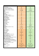
Monitor xL Feature Enhancements
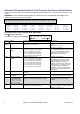
Features Areas Area Groups Area Arm/Disarm Priority Common Area Arm/Disarm Input points (on board - expansion) Output points (on board - expansion) Users Doors Readers per door Floors (per account) Modules LCD Keypad LCD Keypad with Gprox II LCD Keypad with Wiegand Interface Keypad inputs 8 Point Expansion 16 Point Expansion 319.
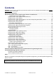
Contents WARNING: Access Control, Suite Security and Elevator selections are only available with the addition of the “Feature Expansion Board” to the system. Advanced Configurations .............................................................................................................................. 1 Advanced Program Sections, Sub Program Sections and Selections .................................................... 2 System Global Timer Delay Codes ..................................................
Disclaimer This document contains proprietary information of UTC CCS Systems, and may not be reproduced in any form or disclosed to any third party without written approval of a duly authorized representative of UTC CCS Systems. All products are warranted against defects in workmanship or materials (details available upon request). Installers are responsible for knowing and complying with any local regulatory fire and building codes.
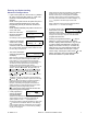
Entering and Understanding Advanced Configurations Logon to the system as a service user. E.g. Default ID: “000”, service user PIN: “2482” or “7378” if the panel has communicated with the Director Software. NOTE: If the system Feature Set (S00200) is 5 or greater, keypad programming can not be done. Programming can only be done with the Director Software. NOTE: Default MASTER (end) USER code is ID 01 or 001, PIN 7793.
Advanced Program Sections, Sub Program Sections and Selections NOTE: For quick reference to locate Advanced Programming Section Selections, consult the Index at the back of this manual. WARNING: Access, Elevator and Suite Security selections are only available with the addition of the “Feature Expansion Board” to the System. Programming selections whose boxes are grey are not available for this version.
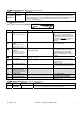
S00101 Keypad Selections (left to right on keypad screen) Default Name Selections WELCOME (16 available characters) Main screen message A greeting message that rotates with any other main screen messages. It can be customized with the cursor under a letter or in a blank space and pressing the desired keypad button to enter a particular letter/number. Use the left and right arrow keys to maneuver back and forth. Use the underscore key “ _ “ on the keypad to insert a space or clear a character.
S00104 Keypad Selections (left to right on keypad screen) Example: 00·0·0·0·0· · Save S00104 Default Name Selections Description 00 Time table codes. (UK ACPO = 18) 0 = All, 1 = 1, 2 = 2, 3 = 3 Primarily for European Users. (UK ACPO = 3) 0 Confirmed Alarm Time Out Maximum Number of Alarms per Point Arming State Menu Navigation 0 LCD Menu Style 0 Unconfirmed Reset Mode Confirm Reset Service 0 (no) (no) (no) (no) Confirm Reset Master Confirm Reset Challenged PIN.
Main Panel Output Examples: If the main panel’s 2 relay outputs have a base of 1; this is the base number they start at. Assigning outputs to them would require the minimum amount of 4. Outputs 3 and 4 are not used. The next set of outputs could be the World Wide Modem with 8 output STU plugged in to the main controller modem port. Its base number would then be 5. 8 outputs assigned to it would make its output range 5 to 12.
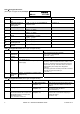
S00200 Keypad Selections (left to right on keypad screen) Default Name Selections 0 Operation Mode 03 Feature Set Description (UK ACPO = 2) Enter from right to left. 0 - Standard version 1- European with modem support 2- UK (DD243) (ACPO) 3-7 – for future extension 1-14 from the following table. This setting determines the system capacity.
S00201 Keypad Selections (left to right on keypad screen) Example: 0·0·0· · Save S00201 Default Name Selections Description 0 User Logon Mode Users can enter their card # at LCD keypad & keypad readers. 0 Service Pin Mode 0 = Standard user ID logon or Card Number logon: 1 = 4 digit, 2 = 5 digit, 3 = 6 digit, 4 = 7 digit, 5 = 8 digit 6 = 9 digit, 7 = 10 digit 0: Permanent 1: Temporary 2 = 6 Digit Pin of the day 0 Escort Required Mode 0 = escorted by users with Escort authority.
S00202 Invalid Cards and PINs Detection Selections Keypad Selections (left to right on keypad screen) Example: 12·12·09·5·0·3· Save Default 12 S00202 Name Selections Description Reset Timeout 1 – 31 (Delay Table), 12 = 2min (0 is meaningless and is not used) The period of time required before there are no further invalid PIN/cards and a “Invalid PIN/Card Condition” resets.
S00203 Keypad Selections (left to right on keypad screen) Default Name Selections 10 (60sec) 0 0 0 Point Reset Time Language Set Remote FW Down/Up Load Arming Rules Description Delay table. Delay time. (UK ACPO = 02) (European = 04) 0=Eng,Fre,Dut,Spa, 1=Eng,Slk,Slk,Slk, 2=Future, 3=Future 0 = Allowed, 1= Must be authorized 0 = Normal operation. Entry/Exit keypad standard tone. 1 = Disarm to off by token. Entry/Exit keypad standard tone. 2 = Constant keypad Entry/Exit tone 3 = Disarm to off by token.
S00302 Primary Card Format—Version Number Keypad Selections (left to right on keypad screen) Default Name Selections (no) Check for Version No. (yes) □ 02 Version No. Position 1 – 40 04 Version No. Length 1–8 Description Whether or not primary-format tokens will be checked for a current version number. The position of the 1st digit for the version number on these access tokens. The length of the version number for primary-format tokens (number of digits). (no) This feature requires V1.
S00400 Secondary Card Format—Site Code Checking WARNING: S00400 – S00405 Access Control related selections are only available with the addition of the “Feature Expansion Board”. Keypad Selections (left to right on keypad screen) Example: ·02·08··········· Save Default Name Selections (no) Check for Site Code Site Code Position (yes) □ Site Code Length 1 – 16 02 S00400 Description Whether or not secondary-format tokens must have a specific site code to be granted entry.
S00403 Secondary Card Format—Basic Settings Keypad Selections (left to right on keypad screen) Example: 10·16·26·8·2···· Save S00403 Default Name Selections Description 10 ID Number Position 1 – 40 16 ID Number Length No. of Bits / Chars 1 – 32 8 Bits per Character 1–8 2 Card/Token Format 0=none, 1=future (dallas), 2=weigand, 3=mag The position of the 1st digit for the ID number on secondary-format access tokens. The length of the card ID-number for secondary-format tokens.
S00500 Dialer Selections Keypad Selections (left to right on keypad screen) Example: 000000·1·0·0·0 Save S00500 Default Name 000000 Dialer Account Number (Primary) Telco Modem Type 1 = Bell 103, 2 = 8OP STU, 3 = WWMODEM 4 = WWMODEM 8OP STU STU = Subscriber Terminal Unit WW = World Wide (UK ACPO = 2) (European = 3) 0 Telco Alarm Report Mode 0 = not used, 1 = primary, 2 = backup, 3 = dual 4 = future NOTE: “0” turns dialer off and clears all the messages in the buffer 0 Telco Format 0 = SIA
010········ S00503 Keypad Selections (left to right on keypad screen) Example: Save S00503 Default 010 Name Selections Description Telco Country Code 001 = Argentina … 088 = Yemen.
S00507 Keypad Selections (left to right on keypad screen) Default Name Selections Description SIP = Security IP Receiver 000000 0 SIP Account HSC Mode 0 HSC Timeout 0=90sec, 1=3min, 2=5min, 3=10min 0 0=full reporting always, 1=use area emergency/full setting 0 HSC Full Report By Area SIP Baud Rate 0 HSC SIP Auto Set 0= NotUsed, 1=SIP1, 2=SIP2, 3=HSC POD (module) HSC POD (High Security Communications) is a proprietary communications of CSG Security Inc. and not used in all markets.
0 Main Control Board Config Dial Out 0 = No config dial out, 1= internal config dial out, 2 = external config dial out, 3 = IP Configurations dial out from main control board to Director software PC. Internal: main control board plug in modem.
(no) Main Control Board Config Callback Only (yes) □ (no) Telco = Telephone Company S00515 Keypad Selections (left to right on keypad screen) Example: Default 0 00 00 00 00 0 0·00·00·00·00·0· Save S00515 Name Selections Description Telco Comms Test Mode Telco Normal Comms Test Delay Telco Backup Comms Test Delay Telco Comms Test Hour Telco Comms Test Minute Telco Comms Test Day 0=fixed, 1=variable based on backup, 2=variable based on any area out, 3=Daytime Schedule Delay table Delay table
S00701, 05, 09,13 Circuit Band Definitions (Custom Resistor Values) Keypad Selections (left to right on keypad screen) Example: 0·1·1·1·1········ Save S00701 Name Selections Description Band 1 Band 2 Band 3 Band 4 Band 5 0=Normal, 1=Alarm, 2=Tamper, 3=unused 0=Normal, 1=Alarm, 2=Tamper, 3=unused 0=Normal, 1=Alarm, 2=Tamper, 3=unused 0=Normal, 1=Alarm, 2=Tamper, 3=unused 0=Normal, 1=Alarm, 2=Tamper, 3=unused S00702, 06, 10, 14 Circuit Band Thresholds-1 Name Selections Description Split between b
Program Section: A001 (Areas) A0xx00 Keypad Selections Note: “xx” represents the area number. (left to right on keypad screen) Example: · OFFICE Save A00100 Default Name Selections (yes) Enable this Area (yes) □ “ OFFICE “ (12 characters) Area Name – Description (no) Whether or not this Area is defined. Area 1 is enabled by default, and cannot be deleted. Customize the same as the “Welcome” message.
A0xx02 Keypad Selections Note: “xx” represents the area number. (left to right on keypad screen) Example: 0·2·0·0· ··· Save A00102 Default Name Selections 0 Exit Delay Warning Type 0 = Normal, 1= Warning tone during Exit Delay, 2= Warning continuous 3= Warning continuous + Block arming 2 Pre-Alarm Delay 0=20sec; 1=30s; 2=60s; 3=5min; 4=10m; 5=30m; 6=1hr; 7=1.
A0xx03 Area Schedule Selections Note: “xx” represents the area number. Keypad Selections (left to right on keypad screen) Example: 000·0·0·0·· Save Default 000 A00103 Name Selections Description Area Schedule 00 = none, 01-250 = schedule # 0=30min, 1= 2-hours 2 = Unlimited The schedule used to automate this area and enable all scheduling features (if applicable). Allowed duration for Disarming outside of schedule.
A0xx05 Keypad Selections “xx” represents the area number. WARNING: These Access Control features are only available with the addition of the “Feature Expansion Board”.
A0xx07 Automatic Arming Note: “xx” represents the area number.
A0xx09 “Common to Area” Map Keypad Selections (left to right on keypad screen). Note: “xx” represents the area number. Default Name Selections Description (no) Area 1 to Area 16 All Areas (yes) □ (no) Auto arm /disarm shared areas. E.g. Office area and warehouse area with adjoining lunch room area. – Lunch room is auto armed when BOTH office and warehouse are armed. – Lunch room is auto disarmed when EITHER office or warehouse is disarmed. Cannot select current area.
Program Section: G001 (Group Area) for use with corresponding areas G001 – G016. G0xx00 Keypad Selections Note: “xx” represents the area number. (left to right on keypad screen) Default Name Selections Description (no) Enable Group Area (yes) □ Blank (12 characters) Area Group Name – (no) For use with Area Group Mode S00108 G0xx01 Keypad Selections (left to right on keypad screen) Note: “xx” represents the area number.
M0xx01 Keypad Selections Note: “xx” represents the module number. 24 · 0 · 0 · 0 · 0 · 2 · (left to right on keypad screen) Example: Save ? M00101 Default Name Selections Module Type (number) See Module Selection Numbers below.
M0xx02 Annunciation Map Keypad Selections (left to right on keypad screen) Note: “xx” represents the module number. Default Name Selections Area 1 to Area 16 Area 1 – 16: (yes) (yes) □ Description (no) M0xx03 Arm/Disarm Map Keypad Selections (left to right on keypad screen) Note: “xx” represents the module number.
M0xx06 Keypad Selections Note: “xx” represents the module number. WARNING: These Access Control features are only available with the addition of the “Feature Expansion Board”. (left to right on keypad screen) Default Name Selections 01 Door Number 03 Hold time (or MultiBadge time) Description Whether it is the first door or second door on the door module.
M0xx07 Keypad Selections Note: “xx” represents the module number. WARNING: These Access Control features are only available with the addition of the “Feature Expansion Board”. (left to right on keypad screen) Example: ·000·0·0· ··· Save ? M00107 Pressing the keypad button under ? will display the type of module and the module’s input and output ranges.
M0xx08 Keypad Selections Note: “xx” represents the module number. (left to right on keypad screen) Example: 000······ Save ? M00108 WARNING: These Access Control features are only available with the addition of the “Feature Expansion Board”.
Program Section: P001 (Inputs) Pxx100 Keypad Selections Note: “xx1” represents the input number. (left to right on keypad screen) Example: 201·01·01········· Save ? P00100 Pressing the keypad button under ? will display the module the point is associated with and the module’s point range. Default Name Selections Description Example: 201 Circuit Type Example: 201 Point Type 01 Area this input is assigned to. 01 Buffer Area 0: N/C (no EOL) 1: N/C with 2.
Default North American Input Settings (Pxx1:00 and Pxx1:01) Input Pt. Circuit/Pt.
E0xx01 Keypad Selections (left to right on keypad screen) Note: “xx” represents the module number.
Program Section: B001 (Programmable Outputs) (left to right on keypad screen) Example: Pressing the keypad button under ? will display the location (main panel, module) of the output and the location’s output range. ? S000 . 05 Query Save ? B00100 Outputs are programmable electronic switches that can be used to signal alarms or control items such as lights, garage doors, etc.
Undefined Output LCD Screen An Undefined Output is ? 0000.00 Undef turned off. It can be Save ? Bxxx:0 changed to any “Query Condition” by changing the first 0 to the letter of any programming section i.e. “S” for System, “A” for Area etc. (see page 1 for a full list). using the Director Software and sent to the panel with a communications method e.g. direct connection, IP module.
Output Examples Examples 1 to 5 are configurable in LCD keypad output programming. Examples 6 to 9 must be configured with the Director software and Sent to Panel. Example 1: Simple Single Equation with Follow Output Bxxx:0 Bxxx:1 “? D025.00 Query ” “T 000 Timer ” - Schedule 25 is in schedule - Follow (Normal) Output Bxxx will be ON whenever schedule #25 is in effect. Example 2: Simple Single Equation with Inverting Output Bxxx:0 Bxxx:1 “? D025.
Example 7: Simple Two Term OR Equation with Timed Output Configurable only with Director software and Sent to Panel Bxxx:0 Bxxx:1 Bxxx:2 “? A001.15 Query ” “? A002.14 Query ” “L 00 Logic ” - Area 1 is not ON - Area 2 is OFF - Logical OR operator Bxxx:3 “T 012 - Timed output, 2 minutes – additional screen generated with Director software. additional screen generated with Director software. 1.
Default System Programmable Outputs North America Output # / Location Default Codes / Setting Meaning / Operation B001:0 (motherboard) B001:1 “? S000.07 Query ” “T 000 Timer ” - Follows Alarm Siren - Follow (Normal) B002:0 (motherboard) B002:1 “? S000.05 Query ” “T 000 Timer ” - When system is IN ALARM. - Follow (Normal) B003:0 (keypad) B003:1 “? A001.01 Query ” “T 005 Timer ” - Function Key 1 on Area 1 1 keypad. - Positive trigger, 10 sec delay. B004 - B128 “? 0000.
Output Selections Table 29 Pseudo 11 – Module Trouble WARNING: Access Control related outputs can only be used with the addition of the “Feature Expansion Board”. 30 Pseudo 12 – Module Battery Low 31 Pseudo 13 – Module Program Edit 32 Pseudo 14 – Module Program Error Program Section (“q”) Section Range (“nnn”) “S”ystem Code “cc” 000 – 000 33 Pseudo 15 – Misc. Trouble Description 34 Pseudo 16 – SIP Trouble Fallback sonalert (at control panel) if Module Bus fails. Provides 1 sec.
Program Section (“q”) Section Range (“nnn”) “D” Schedule Enter 001 – 050 Description Code “cc” 00 Schedule in Schedule 01 15 minutes prior to In Schedule (opening) 02 15 minutes prior to Out of Schedule (closing) 03 Holiday in Effect (Whether Type 1,2,3 or No Access) 04 No Access, Holiday in effect.
European Version (Area) 63 Siren 64 Confirmed Alarm Strobe 65 Fire 66 Personal Attack 67 Unconfirmed Alarm 68 Set / Unset 69 Program Section (“q”) Section Range (“nnn”) “F” loors Code “cc” Enter 001 – 124 00 Description Floor Desecure Program Section (“q”) Section Range (“nnn”) “M” odule Code “cc” Enter 01 – 24 Description Freezer / Fire Fault 00 On Line 70 Bypass in Effect 01 Tamper 71 Confirmed Alarm Program Section (“q”) Section Range (“nnn”) “P”oint (Inputs) Enter 001 –
Program Section: L001 (Authority Levels) L00100 Keypad Selections (left to right on keypad screen) Example: Default Name Selections (yes) First Authority Level Defined? First Authority Level Name (yes) □ MASTER ·MASTER ·· Save L00100 Description (no) Edit the same as the Greeting Message, S001:04 Alphanumeric name for authority level - 12 characters (A blank name field means level is undefined.
Program Section: Q001 (Floor Maps) Q00100 Keypad Selections (left to right on keypad screen) Example: Default 000 000················ Save Q00100 Name Selections Description Schedule 0 = none, 01-250 = schedule # Q00101 – 08 Floor Map Keypad Selections (left to right on keypad screen) Default Name Selections (no) Floor 1 to 16 All Floors (yes) □ (no) Description 1-16 up to 124 Program Section: W001 (User Edit W) W00100 Keypad Selections (left to right on keypad screen) Example: MASTE
Program Section: I001 (Profile I) I00100 Keypad Selections (left to right on keypad screen) Example: ·PROFILE MSTR·· Save I00100 Default Name Selections Description (yes) Profile Defined? PROFILE MSTR Profile Name (yes) □ (no) Edit the same as the Greeting Message, S001:04 Alphanumeric name for authority level - 12 characters (A blank name field means level is undefined.
I00102 Unscheduled Access Related Authority Keypad Selections (left to right on keypad screen) Example: 00·0· ·· Save I00102 Default Name Selections 00 Group Number 0 Group Mode 0 = No Group Authority Group Number 1...
I00105 Scheduled Intrusion Related Authority Keypad Selections (left to right on keypad screen) Example: 1·1·1·1············· Save I005.00 – 005 Cleaner I004.00 – 005 Worker Master Intrusion Emergency Off I003.00 – 005 0=None, 1=Always, 2=Schedule A in effect, 3=Schedule A not in effect 4=Schedule B in effect, 5=Schedule B not in effect 6=Schedule C in effect 7=Schedule C not in effect Employee Door Command Class A Class B Class C Default Authority Settings Description I002.
Program Section: U001 (Users) U00100 Keypad Selections (left to right on keypad screen) Example: MASTER USER 001· Save U00100 Default Name Selections Description MASTER USER 001 User Name Edit the same as the Greeting Message, S001:04 00 = undefined user 01…30 = authority level Alphanumeric name for authority level - 12 characters (A blank name field means user is undefined.) Assign an existing Authority Level number.
Program Section: H001 (Holidays) H00100 Keypad Selections (left to right on keypad screen) Example: Default Name 00 · 00 · 0 Save mm·dd··· H00100 Selections Description Up to 2 digits: 01 – 12 13 = Reserved (for future e.g.
Program Section: T080 (Custom Inputs) T08000 Keypad Selections (left to right on keypad screen) Example: Default 0 00 0 0·00·0· ······ Save T08000 Name Selections Description Level Characteristics 0: 24 hr, 1: Stay & On, 3: On Only See Custom Input Characteristic Types list. 0: Fire Class A (Double Loop); 1: Fire; 2: Hold Up; 3: Aux. Alert; 4: Vault / Safe; 5: Burglary; 6: Supervisory When the input will be monitored. What the special input will do.
T08001 How the input will behave when it is active.
R00101,04 Keypad Selections (left to right on keypad screen) Example: Default (yes) Name st 1 Reader Defined 01 Reader Area 000 Card Lockout Schedule Enable / Disable Card Type (Card Action) Enable / Disable Reader Type (Card 0 0 ·01·000·0·0· Save R00101 Selections Description (yes) □ (no) 2 Digits 01 – 16 00 – outside area 00 = No scheduled lockout 01 – 250 Schedule 00 = None, 01=Escort Req’d, 02 =nonpermanent users, 03 =all users. If enabling reader, see *1 Note below.
R00102, 05 Keypad Selections (left to right on keypad screen) Default Name Selections Description Reader Class Map Schedule Group Number 00 = Treat as In Schedule 01 – 250 Schedule 00 = none, 1 – 63, Reader Group Number. Enter a schedule for reader-class restriction.
R00107 Keypad Selections (left to right on keypad screen) Example: Default 04· 06· 0· · Save R00107 Name Selections Description 04 Unlock Time 06 Challenged Unlock Time 00-31 (Delay Table) 04 = 5 Sec 00-31 (Delay Table) 06 = 15 Sec 0 Door Alarm Monitoring 0=None 1=Door Held Open Processing, 2=Door Forced processing, 3=Door Held Open and Door Forced Processing The unlock duration when a user is granted entry.
R00108 Keypad Selections (left to right on keypad screen) Example: Default 06·10·14·0·0· ···· Save R00108 Name Selections Description 06 Door Held Open Time 10 Challenged Door Held Open Time 00-31 (Delay Table) 06 =15 Sec 00-31 (Delay Table) 10=1 Min 14 Auxiliary Relay Output Time Auxiliary Input Mode How long the door can be held open after access is granted without causing an alarm. How long the door can be held open without causing an alarm after a physicallychallenged user enters.
R00110 Keypad Selections (left to right on keypad screen) Example: Default 000 0 Name Selections Description Unlock Mode Schedule Unlock In Schedule 000 = Treat as In Window setting 001 – 050 (Schedule) 0=Lock, 1=Unlock, 2=Pending First User, 3=Area is OFF, 4=Area Stay/OFF 0=Lock, 1=Unlock, 2=Pending First User, 3=Area is OFF, 4=Area Stay/OFF Enter a schedule for automated door unlocking. The unlock mode for while the schedule is active (or 24 hrs).
R00113 Keypad Selections Forced Open Door Processing (left to right on keypad screen) Example: · · ····· Save Default (no) (no) (no) (no) (no) (no) (yes) (yes) (yes) Name Selections Forced Open Processing Transmit Off Forced Open Processing Transmit Stay Forced Open Processing Transmit On Forced Open Processing Siren Off Forced Open Processing Siren Stay Forced Open Processing Siren On Forced Open Processing Alert Off Forced Open Processing Alert Stay Forced Open Processin
The following program sections are only applied using the Director Software and Feature Expansion Board. Displays in these keypad programming screens are for viewing only. C001 - C060 (Suite Security LED Keypads) Condominium Suite Security LED keypad modules provide security and monitoring features for up to 60 individual suite units associated with a specific main panel. 8 Zone suite security LED keypads support 8 monitored sensors/inputs, 2 programmable outputs, and 3 'panic keys'.
Z001 - Z003 (Shared User Data) Allows Users, Authority Levels and Holidays to be shared across multiple accounts using Director version 4.2. With Director V4.2, this feature is limited to panel feature-set 2, 3, and 4 (1 panel per account, max. 1000 users, etc.). Information for this type of system set-up is available in the v4.2 Director’s User Guide. Shared Users, Authority Levels and Holidays are considered to be under Director control and not panel control.
Transmitted Messages (SIA & Contact-ID) General Message Format Messages are transmitted to the monitoring station using either the "SIA Level II" or "Contact ID" format. NOTICE: The message formats described here are NOT to be confused with messages provided by the receiver software. (Those messages will typically include the information discussed here, along with date/time information and proprietary formatting.
Event Message Reference: Sorted by SIA Code SIA AR AT BA BR BS BT CA CE CF CI CL DG DU EE ER ET FA FR FT HA JR JS JT LB LR LS LT LU LX MA MR MT NF NK+ NL NR+ OA OG OK OP OR PA CID equiv.
(SIA codes--continued from preceding page) RB RC ri RN RO RR RS RU TA TR TS UA UR UT UX0 UX1 UX2 XR XT YC YK YM YP YQ YR YS YT E380 R354 n/a R380 E354 E305 R145 E145 E300 R300 E607 E150 R150 E380 E354 E356 E602 R384 E384 E333 R333 E309 E320 R320 R309 E350 E302 Module Program Changed (E013) Misc Trouble (E015--Restore) Area-number reference Module Program Changed (E013--Restore) Misc Trouble (E015) Time Lost (E006) Module Program Error (E014--Restore) Module Program Error (E014) Main panel Tamper (E001) Ma
(CID codes--continued from preceding page) UX0 Digital Dialer Comms Failure (Messages Lost), or; E354 RO Misc Trouble (E015) UX1 E356 Security IP Comms Failure (Messages Lost, Sync Lost, Reset) FT Fire Class A--Tamper, or; FT Fire--Tamper, or; PT Holdup--Tamper, or; E380 MT Aux. Alert--Tamper, or; QT Vault/Safe--Tamper, or; UT Misc/No Type--Tamper, or; RB Module Program Changed (E013), or; BT E383 Burglary --Tamper XT E384 Module Battery Low--e.g.
European and ACPO Installations Restoring Tampers Once a tamper condition occurs it will be logged within the system’s history log. Tampers can be silenced by any authorized users however, a system message will scroll on the LCD display to indicate that a tamper condition had occurred: “Was in Tamper”.
Output Points When using a switched reporting unit such as the ‘BT Redcare’ the following is recommended: a) Use the 8 output STU (subscriber terminal unit) REDCARE Interface on the World Wide Modem to provide the switched outputs. b) The switched outputs can be configured to monitor the system as a whole or monitor just a single area. The following is the recommended configuration. See “B001 – B128 Programmable Outputs” section for output programming instructions.
The Date of the Pin of the Day program and the site’s system date on its keypad must be the same. UK ACPO Pin of the Day When a UK system is started up for the first time and the new system initialization (explained in Simplified Installation Guide: “Powering On the System for the First Time”) is done selecting UK as the region, the service and master user will need to log on to silence the system. After which, the date and time will display on the keypad for entering.
Index WARNING: Access Control, Elevator and Suite Security selections are only available with the addition of the “Feature Expansion Board” to the System. 1st Reader Defined ............................................................ 51 3rd Party Password for Main Panel ...................................... 3 5 Digit PIN ............................................................................ 7 AC Brownout Mode .............................................................. 4 AC Reference Voltage .....
Enable / Disable Reader Type ........................................... 51 Enable / Disable Setting ..................................................... 51 Enable or Disable Cards of Type ....................................... 29 Enable or Disable Mode ..................................................... 29 Enable this Area ................................................................. 19 Enable Wall Tamper ............................................................. 3 Enabling Reader ..............
Out of Schedule B .............................................................. 52 Out of Schedule C .............................................................. 30 Out of Schedule C .............................................................. 52 Out of Schedule Open ........................................................ 21 Output Examples ................................................................ 36 Output Inverted ...................................................................
Wandering Patient Detect .................................................. 55 Wandering Patient- Lock Doors ......................................... 55 Work Late Time Extension ................................................. 21 21-3602E rev1.
N3459