
User Manual


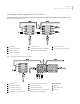


Table Of Contents
- Preface
- Chapter 1 KTD-405/405A/405-2D overview
- Chapter 2 Installation
- Chapter 3 Programming
- Programming modes
- Supervisor programming
- Figure 17. Supervisor programming menu tree
- Figure 18. KB3 PTZ PROTOCOL display
- Figure 19. ENTER REMOTE PRGMG display
- Figure 20. KEYPAD TITLE display
- Figure 21. KEYPAD LOCKOUT PRIORITY displays
- Figure 22. Lowest user programmed preset menu
- Figure 23. PROGRAM SOFT KEYS display
- Figure 24. PRESS KEY TO PROGRAM display
- Figure 25. Command selection display
- Figure 26. Confirm command selection display
- Figure 27. CHANGE ACCESS CODES displays
- Figure 28. BAUD RATE display
- Figure 29. SYSTEM CONTROL display
- Figure 30. INACTIVE TIMEOUT display
- User programming
- Figure 31. OPERATING MODE menu
- Standard Digiplex menus
- Zone menus
- Figure 38. OPERATING MODE menu
- Figure 39. Zone menu
- Figure 40. ENTER ZONE ADDRESS menu
- Figure 41. ZONE xx TITLE menu
- Figure 42. SEND TO ALL KEYPADS display
- Figure 43. Zone hub display
- Figure 44. Zone monitor outputs
- Figure 45. Zone camera inputs
- Figure 46. Access restriction menus
- Figure 47. ZONE xx ACCESS menu
- Figure 48. Annunciation menu
- Figure 49. Call tone menu
- Figure 50. SPOT MONITOR NUMBER menu
- Remote programming
- Chapter 4 Operation
- Operating your keypad
- Standard Digiplex mode
- Figure 55. Normal operating display
- Selecting a monitor
- Selecting a camera
- Controlling a camera
- Setting a preset
- Recalling a preset
- Operating group switching on Digiplex IV switchers
- Setting autopan limits
- Controlling a DVMRe/multiplexer (hybrid mode)
- Controlling a recording device
- System information menus
- Help menu
- Audio
- Zone mode
- Chapter 5 Troubleshooting and support
- Appendix A Sample configurations and charts
- Sample analog system configurations
- Sample IP system configuration
- Receiver site addressing
- Reprogrammable keys and commands
- System planning chart
- Index

Appendix A
Sample configurations and charts
65
Receiver site addressing
Each receiver has a DIP switch used to assign its site address. To determine the receiver site address, see
Table 8, Table 9, and Figure 71 on page 65 and perform the following:
1. Determine which position values must be added together to equal the site number.
2. Place the switches that correspond to those values in the ON position
One way to determine which switches to use is to subtract the highest possible switch value from the address
you want, then subtract the highest possible switch value from that difference. Continue to subtract the highest
possible switch value from the difference until you have zero.
For example, assume you want address 209. The highest value under 209 is 128 (switch 8). Subtracting 128
from 209 yields 81. The highest value under this remainder is 64 (switch 7). Subtracting 64 from 81 yields 17,
and from there you would subtract 16 (switch 5) and 1 (switch 1).
Therefore, for address 209, you would use switches 8, 7, 5, and 1 (equivalent to 128 + 64 + 16 + 1 = 209). See
Figure 71.
Figure 71. Receiver site address DIP switches (set to 209)
Table 8. Dip switch positions and equivalent values
DIP switch position number
12345678910
Equivalent value
1248163264128256512
Site address 209 (128 + 64 + 16 + 1)
12345678910
2
1
= 2
2
2
= 4
2
3
= 8
2
4
= 16 2
5
= 32
2
6
= 64
2
7
= 128
2
8
= 256
2
9
= 5122
0
= 1