
User Manual


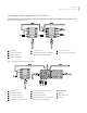


Table Of Contents
- Preface
- Chapter 1 KTD-405/405A/405-2D overview
- Chapter 2 Installation
- Chapter 3 Programming
- Programming modes
- Supervisor programming
- Figure 17. Supervisor programming menu tree
- Figure 18. KB3 PTZ PROTOCOL display
- Figure 19. ENTER REMOTE PRGMG display
- Figure 20. KEYPAD TITLE display
- Figure 21. KEYPAD LOCKOUT PRIORITY displays
- Figure 22. Lowest user programmed preset menu
- Figure 23. PROGRAM SOFT KEYS display
- Figure 24. PRESS KEY TO PROGRAM display
- Figure 25. Command selection display
- Figure 26. Confirm command selection display
- Figure 27. CHANGE ACCESS CODES displays
- Figure 28. BAUD RATE display
- Figure 29. SYSTEM CONTROL display
- Figure 30. INACTIVE TIMEOUT display
- User programming
- Figure 31. OPERATING MODE menu
- Standard Digiplex menus
- Zone menus
- Figure 38. OPERATING MODE menu
- Figure 39. Zone menu
- Figure 40. ENTER ZONE ADDRESS menu
- Figure 41. ZONE xx TITLE menu
- Figure 42. SEND TO ALL KEYPADS display
- Figure 43. Zone hub display
- Figure 44. Zone monitor outputs
- Figure 45. Zone camera inputs
- Figure 46. Access restriction menus
- Figure 47. ZONE xx ACCESS menu
- Figure 48. Annunciation menu
- Figure 49. Call tone menu
- Figure 50. SPOT MONITOR NUMBER menu
- Remote programming
- Chapter 4 Operation
- Operating your keypad
- Standard Digiplex mode
- Figure 55. Normal operating display
- Selecting a monitor
- Selecting a camera
- Controlling a camera
- Setting a preset
- Recalling a preset
- Operating group switching on Digiplex IV switchers
- Setting autopan limits
- Controlling a DVMRe/multiplexer (hybrid mode)
- Controlling a recording device
- System information menus
- Help menu
- Audio
- Zone mode
- Chapter 5 Troubleshooting and support
- Appendix A Sample configurations and charts
- Sample analog system configurations
- Sample IP system configuration
- Receiver site addressing
- Reprogrammable keys and commands
- System planning chart
- Index

KTD-405/KTD-405A/KTD-405-2D Controller Keypad
User Manual
64
Sample IP system configuration
In Figure 70, the four IP sources are GE Legend IP domes. The domes’ ID addresses need to be programmed
as #17, #18, #19, and #20 as the IP inputs. To control them you should have the PTZ units site address set to 16,
17, 18, and 19.
The SymDec 16 plus 4 is capable of recording 16 analog video signals and 4 IP streamed video signals. Any
video source can be a PTZ (pan/tilt/zoom) device. Only a KTD-405 keypad or SymNav may be used to control
a PTZ device. Figure 70 is an example of a SymDec single-zone system configuration.
Note: All GE IP dome’s addresses are always one number lower than the physical input number on the SymDec 16 plus 4.
Figure 70. SymDec 16 plus 4 single-zone system configuration
We have upgraded KTD-405 and SymDec 16 firmware to allow this new functionality. The latest KTD-405
firmware includes a new device type, SymDVR, now available in the hub list. Installers using zone mode can
now select analog and IP cameras connected to the SymDec device in sequential order.
In the SymDec device firmware upgrade, the SymDec device now assigns the cameras attached to the IP ports
as the next device ID following the last analog port. For a SymDec with 16 analog ports and 4 IP ports, the IP
ports will address cameras 16, 17, 18, and 19 (zero base ID).
To upgrade your KTD-405, order part #1037271 from GE Security. The upgrade kit consists of two EPROMs
with the updated firmware, version 1.4
. To upgrade your SymDec device firmware, open a browser window,
and navigate to http://www.gesecurity.com/videoupgrades. Click on the Current Product Flash Upgrade Files
link. Click on the SymDec16 plus 4 link, and then read the instructions on the page.
Video
Ethernet
PC with SymNav
Ethernet Switch
16 analog cameras
SymDec 16 plus 4
Monitor A
IP Camera 1
Address 17
IP Camera 4
Address 20
IP Camera 2
Address 18
IP Camera 3
Address 19
Monitor B
KTD-405 keypad
controller