
Installation Instructions
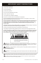
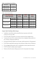
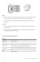
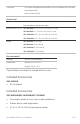
Table Of Contents

4 of 9 P/N 1069682 • REV 1.0 • ISS 14APR10
Table 1: Loop Resistance per 1000 feet
Wire Type Resistance
24 AWG /0,53 mm 52 ohms
23 AWG /0,57 mm 42 ohms
22 AWG /0,64 mm 33 ohms
Table 2: Power Distance Chart
Power Supply Voltage 12 VDC 24 VAC 28 VAC
Voltage at the Camera 10.8 VDC 21.6 VAC 21.6 VAC
Dual 24 AWG 448 ft. / 137 m 896 ft. / 273 m 2,388 ft. / 728 m
100 mA Camera
Dual 23 AWG 564 ft. / 172 m 1,130 ft. / 345 m
3,012 ft. / 918 m
Dual 24 AWG 150 ft. / 46 m 300 ft. / 92 m 796 ft. / 243 m
300 mA Camera
Dual 23 AWG 190 ft. / 58 m 378 ft. / 115 m 1,004 ft. / 306 m
Dual 24 AWG 46 ft. / 14 m 90 ft. / 28 m 240 ft. / 73 m
1 AMP Camera
Dual 23 AWG 58 ft. / 18 m 114 ft. / 35 m 300 ft. / 92 m
Important Safety Warnings
• Installation should be made by a qualified service person and should
conform to all local codes.
• DO NOT bundle UTP signals in the same conduit as high-voltage wiring.
• To reduce the risk of fire or electrical shock, do not expose these products to
rain, moisture, dripping or splashing.
• No objects filled with liquids, such as vases, shall be placed on GE equipment.
• DO NOT block ventilation openings to let sufficient airflow to the UTP devices.
• Only unplugging the power cord is considered as a main power disconnect.
• DO NOT connect multiple outputs together.
• Make sure that the mains Voltage input is set to the proper local voltage.