
Installation Instructions
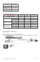
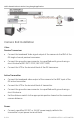
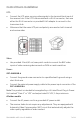
Table Of Contents

P/N 1069681 • REV 1.0 • ISS 14APR10 7 of 11
Control Room Installation
UTP:
• Connect the UTP wires carrying video signals to the terminal block input of
the receiver hub. If the UTP is terminated with a RJ-45 connector, then use
either the RJ-45 connector or provided RJ-45 adapter to connect to the
transceiver hub.
• Make sure that the same UTP pair and polarity are used on both transmit
and receive sides.
Video:
• Use provided 2-foot (60 cm) coax patch cords to connect the BNC video
inputs of video receiving devices such as DVRs or matrix switches.
Power:
GEC-4VARHUB-4
• Connect the ground screw connector to a qualified earth ground using a
short thick wire.
• Connect the external power supply cable to the power input connector of the
GEC-4VARHUB-4.
Note: This product is intended to be supplied by a UL Listed Direct Plug-In Power
Unit marked “Class 2” or “LPS” and output rated 12 VDC, 1 Amp minimum.
All other models
• Connect the AC power cord to a grounded AC power outlet.
• The receiver hubs do not require any adjustments. They are equipped with
Automatic Video Compensation (AVC) circuit that automatically adjusts the
video quality regardless of video content.