
Installation Instructions
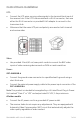
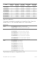
Table Of Contents
2 of 11 P/N 1069681 • REV 1.0 • ISS 14APR10
The following model numbers are covered in this document:
• GEC-4VARHUB-4
• GEC-8VARHUB-4
• GEC-16VARHUB-4
• GEC-32VARHUB-4
• GEC-8VARHUB-6.5
• GEC-16VARHUB-6.5
• GEC-32VARHUB-6.5
Important Safety Warnings
• Installation should be made by a qualified service person and should
conform to all local codes.
• DO NOT bundle UTP signals in the same conduit as high-voltage wiring.
• To reduce the risk of fire or electrical shock, do not expose these products to
rain, moisture, dripping or splashing.
• No objects filled with liquids, such as vases, shall be placed on GE equipment.
• DO NOT block ventilation openings to let sufficient airflow to the UTP devices.
• The Main fuse for models with built-in AC power supply is 5 A at 110 VAC or
at 3 A 220 VAC. Each camera power fuse is 2 A and can be accessed by
removing the front panel. Fuses may be replaced by a qualified service
person only when the unit is off and AC power cord is unplugged.
• Use only the power cord and plug supplied with the unit for connecting to AC
outlets.
• Only unplugging the power cord is considered as a main power disconnect.
• DO NOT connect multiple outputs together.
• Make sure that the mains Voltage input is set to the proper local voltage.