TruVision DVR 42 User Manual P/N 1072662B-EN • REV 1.
Copyright © 2014 United Technologies Corporation. Interlogix is part of UTC Buildings & Industrial Systems, a unit of United Technologies Corporation. All rights reserved. Trademarks and patents Trade names used in this document may be trademarks or registered trademarks of the manufacturers or vendors of the respective products. Manufacturer Interlogix. 2955 Red Hill Avenue, Costa Mesa, CA 92626-5923, USA Authorized EU manufacturing representative: UTC Fire & Security B.V.
Content Chapter 1 Product introduction 5 Product overview 5 Default settings to access the device 5 Chapter 2 Installation 7 Installation environment 7 Unpacking the TVR 42 and its accessories 7 Back panel 8 RS-485 ports 9 RS-232 port 10 Monitor connections 10 Loop through 10 Audio inputs and output 10 Brackets 11 PTZ dome camera set up 11 Wiring the KTD-405 keypad 16 Chapter 3 Getting started 19 Turning on and off the DVR 19 Using the setup wizard 20 Chapter 4 Operating instructions 24 Controlling t
Setting and calling up presets 49 Setting and calling up preset tours 51 Setting and calling up a shadow tour 52 Chapter 7 Playing back a recording 54 Overview of the playback window 54 Playback pop-up menu 56 Instant playback 57 Previous-day playback 58 Searching recorded video 59 Playing back recordings by time and video type 60 Playing back recordings by event 61 Creating and playing back bookmarked recordings 62 Slideshow of snapshots 63 Playing back recordings from the system log 64 Playback skip time
External alarm schedules 96 Protecting recorded files 96 HDD redundancy 98 Chapter 11 Alarm settings 100 Description of alarm notification types 100 Setting up motion detection 103 Setting up external alarms 106 Triggering or clearing alarm outputs manually 108 Setting up system notifications 108 Detecting video loss 109 Detecting video tampering 110 Chapter 12 Network settings 111 Configuring general network settings 111 Configuring PPPoE 112 Configuring DDNS 113 Configuring an NTP server 114 Configurin
Chapter 15 DVR management 132 Configuring the RS-232 port 132 Updating system firmware 133 Restoring default settings 134 Viewing system information 134 Searching system logs for events 137 Importing and exporting configuration settings 138 Chapter 16 User management 139 Adding a new user 139 Customizing a user’s access privileges 140 Deleting a user 142 Modifying a user 142 Changing the Admin password 142 Appendix A Specifications 143 Appendix B PTZ protocols 145 Appendix C Port forwarding informa
Chapter 1 Product introduction Product overview The TruVision™ DVR 42 (TVR 42) is a versatile, user-friendly embedded digital video recorder (DVR) allowing end-users to record 4, 8, or 16 analog cameras at 960h in real time (25/30 fps), while providing integration with the UTC portfolio of security solutions, and offering a seamless product experience within the TruVision brand. Its dual streaming functionality allows the user to set up different settings for recording and streaming video in live view mode.
User Description Guest The default user name is “guest”. The default password is 3333. Note: The default passwords should be changed for security reasons. Default network settings The default values for TVR 42 network settings are: • IP address - 192.168.1.82 • Subnet mask - 255.255.255.0 • Gateway address - 192.168.1.
Chapter 2 Installation This section describes how to install the TVR 42 unit. Installation environment When installing your product, consider these factors: • Ventilation • Temperature • Moisture • Chassis load Ventilation: Do not block any ventilation openings. Install in accordance with the manufacturer’s instructions. Ensure that the location planned for the installation of the unit is well ventilated.
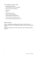
Items shipped with the product include: • IR (infrared) remote control • Two AAA batteries for the remote control • AC power cords (US, Europe, UK) • USB mouse • TVR 42 • Video loop through cable • CD with software and manuals • TruVision DVR 42 Quick Start Guide • TruVision DVR 42 User Manual (on CD) • TruVision Recorder Operator Guide (on CD) Back panel Figure 1 on page 9 shows the back panel connections and describes each connector on a typical TVR 42 digital video recorder.
Figure 1: Back panel connections 1. Connect up to 16 analog cameras to BNC connectors (depends on the DVR model). 2. Connect audio inputs (available for each camera) to RCA connectors. 3. Connect up to two CCTV monitors (BNCtype connectors): - Spot monitor - Main monitor 4. Connect to speakers for audio output. 5. Connect RCA connector to a microphone. 6. Connect to a RS-232 device. 7. Connect one CCTV monitor (BNC-type connector). 8. Connect to an optional eSATA device such as SATA HDD, CD/DVD-RM. 9.
G: Ground of dome camera G: Ground of keypad • Keyb: Connect the keypad. Figure 2: RS-485 pins RS-232 port Use the RS-232 port to connect CBR-PB3-POS (point-of-sale) and ATM devices to the DVR. See “Configuring the RS-232 port” on page 132 to configure the port. Monitor connections Connect the monitors to the DVR outputs (BNC/VGA/HMDI). The HDMI version is 1.3. The unit provides a 1 Vp-p analog signal. See Figure 1 on page 9 for connecting a monitor to a TVR 42.
Audio input RCA jack, 315 mV, 40 kohms. Unbalanced Audio output RCA jack, 315mV, 600 ohms. Unbalanced Note: Line-level audio requires amplification. Brackets The DVR is easily rack-mountable with the purchase of the TVR-RK-1 rackmount kit. See Figure 3 below. Contact your local supplier to order it. Figure 3: Rack-mount installation To install the racks: 1. Attach the two small front-rack mount ears to the DVR (A). The screws are supplied. 2.
See Appendix B on page145 for the supported protocols and Appendix F on page 158 for the PTZ commands supported by each protocol. Each PTZ camera must be set up individually. For information on configuring PTZ dome camera settings, see Chapter 6, “Controlling a PTZ camera” on page 47. Connecting a TVR 42 to a PTZ dome camera and a keypad You can connect the KTD-405 or TVK-800 keypad to the DVR. The KTD-405 is a RS-485 bus keypad and the TVK-800 is an IP keypad.
Table 2: PTZ protocols for Interlogix cameras Camera Switch setting TruVision Mini PTZ Protocol DIP 12X: Indoor Dome switches: 000000 RS-485 communication DIP switches: 0000000000 Camera ID DIP switches: Select the camera ID DIP switch address as required 1. Protocol DIP switches 2. RS-485 communication DIP switches 3.
Camera Switch setting TruVision Dome 16X PTZ Protocol switches: 0111 Address switches: Select the camera ID DIP switch address as required. Baud rate: 0000 1. Address switches; 2. Baud switches; 3. Protocol switches RS-485 data connector: CyberDome Protocol switches: NA Address switches: Select the camera ID DIP switch address as required.
Camera Switch setting UltraView PTZ Protocol switches: 01000 Address switches: Select the switch address as required. 1. Protocol switches; 2. Address switches RS-485 data connector: Legend Protocol switches: 1 Address switches: Select the camera ID DIP switch address as required.
Wiring the KTD-405 keypad The KTD-405 keypad uses RS-485 simplex wiring. The signal is transferred by a single twisted pair line. A shielded STP CAT5 network cable is recommended. Ground one end of the cable, either the first or last device on the RS-485 line. The maximum number of devices that can be installed in one bus is 255, with a maximum cable length of 1200 m. The cable length can be expanded using a signal distributor.
Figure 6: Star wiring with RS-485 signal distributor Correct: 1. Keypad (KTD-405 keypad shown) 2. I/O box 3. RS-485 distributor 4. See section “RS-485 ports” on page 9 Incorrect: 1. Keypad (KTD-405 keypad shown) 2. I/O box 3. See section “RS-485 ports” on page 9 Use an RS-485 signal distributor to increase the maximum number of devices on the bus as well as the total range. Each distributor output provides another RS485 bus, extending the output an additional 1200 m.
Figure 7: Expanding the system with an RS-485 signal distributor 1. Keypad (KTD-405 keypad shown) 2. I/O box 3. RS-485 distributor 4. See section “RS-485 ports” on page 9 Caution: Most signal distributors are unidirectional. This means that the signal only flows from the input towards the outputs. Consequently it is not possible to connect several keypads. See section “RS-485 ports” below to configure the RS-485 port communication settings.
Chapter 3 Getting started Turning on and off the DVR Before starting the power up process, connect at least one monitor to the BNC, HDMI, or VGA outputs. Otherwise, you will not be able to see the user interface and operate the device. Also connect at least one camera. The DVR auto-detects the video mode (PAL or NTSC) on startup. It is equipped with a universal power supply that will auto-sense 110/240 V, 60/50 Hz.
Using the setup wizard The TVR 42 has an express installation wizard that lets you easily configure basic DVR settings when first used. It configures all cameras simultaneously. The configuration can then be customized as required. By default the setup wizard will start once the DVR has loaded. It will walk you through some of the more important settings of your DVR. Any changes you make to a setup configuration page are saved when you exit the page and return to the main wizard page.
Note: The system time and date are visible on screen. However, they do not appear in recordings. Click Next to move to the next page, or Previous to return to the previous page. 7. Network configuration: Configure your network settings such as the NIC type, IP address, subnet mask and default gateway. Enter the preferred DNS server address as well as the alternate one to use. Click Next to move to the next page, or Previous to return to the previous page. 8.
9. Recording configuration: Configure your recording settings as required. The settings apply to all cameras connected to the DVR. There are two recording configurations: Auto record settings: The window for “Auto Record Settings” is shown below. Advanced record settings: The window for “Advanced Record Settings” is shown below. Check the Constant Recording checkbox for the DVR to record continuously all day. If left unchecked, the DVR will not record.
Click Finish to exit the Wizard. The TVR 42 is now ready to use.
Chapter 4 Operating instructions Controlling the TVR 42 There are several ways to control the DVR: • Front panel control • Mouse control • IR remote control • KTD-405 keypad control (see Appendix) • Web browser control You can use your preferred control method for any procedure, but in most cases we describe procedures using mouse terminology. Optional control methods are given only when they differ substantially from mouse control methods.
Figure 8: Front panel The controls on the front panel include: Item Name Description 1. USB port The recorder supports additional devices such as a USB mouse, CD/DVD burner, and a USB HDD on the front and rear USB ports. 2. Eject button Ejects CD/DVD disc. 3. Archive button Press once to enter quick archive mode. Press twice to start archiving. 4. CD/DVD slot Insert a CD or DVD disc. 5. Display buttons Display: Toggles through the various multiviews: full, quad, 1+5, 1+7, 9, and 16.
Item Name Description 8. Status LEDs HDD: A steady green light indicates that the recorder is accessing the HDD in read or write mode. A steady red indicates a HDD failure. Network: A steady green light indicates that the recorder is currently connected to a network. No light indicates that it is not connected to a network. Internal: A steady green light indicates that the recorder is recording video or audio. No light means that it is not recording.
Item Name Description 14. Menu and Search buttons Menu: Enter/exit the main menu. Search: In live view mode, enter the advanced search menu. Using the mouse The USB mouse provided with the DVR can be used to operate all the functions of the DVR, unlike the front panel which has limited functionality. The USB mouse lets you navigate and make changes to settings in the user interface. Connect the mouse to the DVR by plugging the mouse USB connector into the USB port on the back or front panel.
Using the IR remote control The TVR 42 is supplied with an infra red (IR) remote control unit. Like the mouse, it can be used to operate all of the main functions of the TVR 42. The IR remote control can be programmed with a unique device ID address so that the controller will only be able to communicate with DVRs with that address. No programming is necessary if using a single TVR 42. The device ID address only applies when using a remote control and not when using a keypad.
Item Description 7. Menu Activate the main menu. 8. Seq Start /stop sequencing. 9. , , , In Menu mode: Use left or right arrow buttons to select and up or down arrow buttons to edit entry. In PTZ mode: Use to control PTZ. In Playback mode: Use to control playback speed. 10. OK Confirm selection. 11. Zoom + and - Use to control zoom of camera lens. 12. Preset Enter preprogrammed three-digit code to call up a preset. 13. Tour Enter preprogrammed three-digit code to call up shadow tour. 14.
• Check the battery polarity. • Check the remaining charge in the batteries. • Check that the IR remote control sensor is not masked. If the problem still exists, please contact your administrator. Menu overview The TVR 42 has an icon-driven menu structure that allows you to configure the unit’s parameters. Each command icon displays a dialog window that lets you edit a group of settings. Most menus are available only to system administrators. The configuration window is divided into three sections.
Icon Name Description Camera management Configures camera settings including OSD display, motion detection, video image adjustments, camera title, privacy mask, tamper-proof, video loss, coverts camera, and copy settings to other cameras. See Chapter 14 “Camera settings” on page 128. Video schedule Configures recording settings including recording schedules, record quality, auto delete mode, manual record, overwrite, v-stream encoding, auto archive, and recording mode.
4. Click Back to return to live view. Using the soft keyboard A keyboard will appear on-screen when you need to enter characters in a window option. Click a key to input that character.
Chapter 5 Live view Description of live view Live view is the normal operating mode of the unit where you watch live images from the cameras. The TVR 42 automatically enters into live view once powered up. On the monitor, you can see the current date and time, camera name, and whether a recording is in progress. Status information Information on the system and camera status is displayed as icons on the main and spot monitors. The camera status icons are shown for each camera.
Video output The recorder automatically checks the monitor outputs used. If more than one monitor is connected, it then defines which monitor is the main one and which is the event one. The spot monitor is used to display detected events such as motion. Only one monitor can be controlled at a time. If a HDMI monitor is used, it will be the main output. If HDMI and VGA monitors are both connected to the DVR, both will be main monitors; they will both show the same view.
Figure 12: The mouse menu for the main monitor The list of commands available depends on which monitor is active; main or spot (monitor B). See Table 7 below. The default settings of these commands are provided in Appendix G “Default menu settings” on page 160. Table 6: Mouse menu for monitor A (main monitor) Item Name Description 1. Menu Enter the Main menu. This option is not available from monitor B. 2. Single Camera Switch to a full-screen view for the selected camera from the dropdown list.
Note: When the monitor B is active, the main monitor commands are unavailable. Table 7: Mouse menu for monitor B (spot monitor) Item Name Description 1. Single camera Switch to a full-screen view for the selected camera from the dropdown list. 2. Multi camera Switch between the different multiview options from the dropdown list. 3. Previous screen In single-camera mode, display the previous camera. In multi-camera mode, display the previous screen cameras. 4.
Figure 13: Multiview display formats To select a multiview format: 1. Press the Display button on the front panel to cycle through different display formats. You can also right-click the mouse and select Multi Camera from the menu. Select the desired multiview display layout. Sequencing cameras The sequencing feature allows a camera to be displayed briefly on screen, before advancing to the next camera in the sequence list. Sequencing can only be done in full screen mode.
Figure 14: Quick access toolbar Table 8: Description of the quick access toolbar icons Icon Description Freeze: Freeze the live image of the selected camera. Although the image pauses, time and date information does not. The system clock continues to run. Manual record: Start/stop manual recording. The icon is red when manual recording is enabled. See “Manual recording” on page 95 for information on setting up this function.
Digital zoom You can easily zoom in or out of a camera image in live view and playback using the digital zoom command. The zoom command magnifies the camera image four times. See Figure 15 below. Figure 15: Digital zoom window To quickly zoom in/out on a camera image: 1. Left-click the mouse on the desired camera. The quick access toolbar appears. 2. Left-click the mouse and select the digital zoom icon, or on the front panel press the Zoom+ button. The digital view window appears. 3.
Figure 16: Layout window Table 9: Description of the layout window Submenu name Description General tab 1. Video output interface Select which monitor will be the main monitor: HDMI (depends on DVR model), VGA, main analog or spot output. Default is VGA, if connected. 2. Live view mode Select which multiview layout will be default in live view mode. Default is 4x4 multiview layout. 3.
Changing the camera sequence The cameras are sequenced in numeric order by default. You can change the sequence order of the cameras for VGA/HDMI, analog, and spot monitors. You can switch the channel of a camera with that of another camera in the system. This lets you, for example, have the images of camera 1 appear on channel 10, and the images of camera 10 appear on channel 1.
Camera sequencing for alarms and events You can select which monitor is used to sequence alarm and event cameras in full screen mode. Normally this is the spot monitor. When an alarm or event occurs, the selected monitor will sequence through the alarm/event cameras depending on the dwell time set up. You can set up different dwell time for alarms and events. To set the camera sequencing for alarms and events: 1. Click the Display Mode Settings icon in the menu toolbar. 2. Select Layout > General. 3.
Table 10: Description of the time and date settings window Option Description 1. Time Zone Select the time zone of the DVR from the drop-down list. 2. Date Format Select the date format from the drop-down list. Default format is DD-MM-YYYY. 3. Time Format Select the time format from the drop-down list. Default format is 24hour format. 4. Display Week Display the day of the week in the monitor time bar. Check the box to enable/disable. Default format is Disable. 5.
• Manually change the video output format (PAL/NTSC) • Change the time out period after which the display reverts to showing live view • Enable/disable the transparency of the menus on screen • Enable/disable whether the status icons appear on screen See Figure 19 below and Figure 20 on page 45. The changes are immediately implemented once Apply is clicked to save the settings.
Option Description 8. Scaling output video Enable/disable the monitor display of the main and spot monitor size to accommodate for differently sized monitors. Check the box to enable/disable and click Apply. 9. Enable wizard Define whether the wizard tool starts when the DVR is turned on. Check the box to enable/disable and click Apply.
Option Description Other Notification: Panel Alarm LED Check to enable the Motion alarm option. Motion Alarm Define whether the status LEDs on the front panel start flashing when motion is detected. Check the box to enable/disable and click Apply. Instant Playback Time Modify the instant playback replay period. The time options are between 5 and 30 minutes from the actual time. Default is five minutes.
Chapter 6 Controlling a PTZ camera You can control PTZ dome cameras using the buttons on the front panel, the keypad, and IR remote control as well as using the PTZ control panel accessed with the mouse. Access to PTZ commands may require a password. A detailed list of the PTZ commands available for many different camera protocols is available in Appendix F on page 158. Configuring PTZ settings Use the PTZ Settings menu to configure the PTZ dome cameras. Each camera must be set up individually.
Calling up presets, preset tours and shadow tours When in live view you can quickly call up the list of existing presets, preset tours and shadow tours by using the front panel, remote control, mouse and keypad. Front panel Press the joystick to Enter. PTZ control panel appears. Mouse Right-click the mouse on the desired camera image. The quick access toolbar appears. Click the PTZ control icon to enter PTZ mode. The PTZ control panel appears. Remote control Press the OK button.
Name Description Jumps to the home position. 5. Select PTZ command Displays the desired function from the scroll bar: camera, preset, preset tour or shadow tour. 6. Open/close menu Opens/closes the PTZ command section of the PTZ control panel. 7. Exit Exits the PTZ control panel. Setting and calling up presets Presets are previously defined locations of a PTZ dome camera. It allows you to quickly move the PTZ dome camera to a desired position.
Name Description Deletes the selected shadow tour. 4. Preset tour toolbar Adds a step to a selected preset tour. Starts the selected preset tour. Stops the selected preset tour. Deletes all the preset tour steps. Scroll up the list. Scroll down the list. 5. PTZ control panel See “Calling up presets, preset tours and shadow tours” on page 48 for more information. To set up a preset: 1. From the menu toolbar, click PTZ Settings > More Settings. 2.
Setting and calling up preset tours Preset tours move a PTZ dome camera to different steps (called “Keypoint” in the interface). The camera stays at a step for a set dwell time before moving on to the next step. The steps are defined by presets (see “Setting and calling up presets” on page 49.) Each preset tour consists of steps. A step consists of a step number, a dwell time, and a speed. The step number is the order the camera will follow while cycling through the preset tour.
6. Click Back to return to live view. To delete a preset tour: 1. From the menu toolbar, click PTZ Settings > More Settings. 2. From the preset list, select a tour number and click the preset tour. to delete the selected – Or – In the preset tour toolbar, click selected tour. to delete all the preset tours for the 3. Click Back to return to live view. To call up a preset tour: • PTZ control panel: 1. In live view left-click the mouse and select the PTZ control icon in the quick access toolbar.
3. To record a new shadow tour, click and use the directional buttons on the PTZ control panel to move the camera along the desired path. 4. Click to save the shadow tour. Note: The shadow tour can be overwritten. 5. Click Back to return to live view. To call up a shadow tour: • PTZ control panel: 1. In live view left-click the mouse and select the PTZ Control icon in the quick access toolbar. The PTZ control panel appears. Select the desired camera from the toolbar.
Chapter 7 Playing back a recording The TVR 42 lets you to quickly locate and play back recorded video. There are four ways to play back video: Instant playback of the most recently recorded video All-day playback of the day’s recorded video Search the video archives by specific time, date, bookmark, snapshot, or event Search the system log The DVR continues to record the live view from a camera while simultaneously playing back video on that camera display.
Figure 23: Playback window 1. Playback viewer. 2. Camera panel. Select the cameras for playback. Move the mouse over the area to display the list of cameras available.. 3. Calendar panel. Blue: Current date Yellow: Recordings available on the DVR 4. Playback control toolbar. See Figure 24. The playback control toolbar It is easy to manually control playback using the playback control toolbar. See Figure 24 below. Note: The control toolbar does not appear for instant playback.
Item Description 2. Zoom control: Zoom in and out of the timeline to show the progress bar in greater or lesser detail. 3. Playback control toolbar: Reverse play the recording. Click again to pause. Stop playback. Timeline jumps back to 00:00 time (midnight). Play recording. Forward skip by 30 seconds. Reverse skip by 30 seconds. Decrease playback speed: Options available are: single frame, 1/8 speed, ¼ speed, ½ speed, normal, X2 speed, X4 speed, X8 speed, maximum speed. Increase playback speed.
Figure 25: The playback pop-up menu Item Name Description 1. Camera Select a camera for playback. 2. Digital zoom Enter the digital zoom function for the selected camera. 3. Motion search Call up the motion search toolbar to search playback recording for incidents of motion detection. See “Motion search” on page 65 for more information. 4. Text show Display inserted text on screen. 5. Skip time Modify the playback skip time. See “Playback skip time” on page 65 for more information. 6.
3. Click Pause Click Play Click Stop on the toolbar to pause playback. to restart playback. to stop playback and return to live view. To change the instant playback time period: 1. Click Display > Monitor > More Settings in the menu toolbar. 2. Select the desired instant playback time: 5, 10, 20, or 30 minutes. The default time is 5 minutes. 3. Click Apply. Previous-day playback Use this option to play back recorded video from the previous day. Playback starts at midnight and runs for the 24-hour period.
Right-click the mouse and click Exit from the mouse menu to return to the previous window. • Using the front panel: 1. Select the camera for playback and press the Replay button. Playback from the selected camera starts immediately. Note: Multiview playback is only available using the mouse. If live view was showing multiview, only the camera in the top-left channel on screen will be played back. 2. To select a different camera for play back, press the numerical button of the desired camera. 3.
Figure 26: Example of a search result list Playing back recordings by time and video type You can search recorded video by time and video type, such as continuous recordings, motion, text insertion, alarm and all recordings. Video can be played back simultaneously across several cameras. To play back search results: 1. In live view mode right-click the mouse and in the mouse menu select Advanced Search > Normal. 2.
Click Exit window. in the playback control toolbar to return to the search results - Or Right-click the mouse and select Exit from the list to return to the search results window. - Or Right-click the mouse and select Video Search from the list to return to the search window. Playing back recordings by event You can search recorded video by event type: motion, alarm input, and POS/ATM text insertion. Video can be played back simultaneously across several cameras. To play back search results: 1.
- Or Right-click the mouse and select Exit from the list to return to the search results window. - Or Right-click the mouse and select Video Search from the list to return to the search window. Creating and playing back bookmarked recordings You can bookmark the important scenes in a recorded file for later reference. Bookmarks flag the start of a scene. Up to 64 bookmarks can be saved in a video file. There are two types of bookmarks: • Default bookmark “Bookmark”.
Click Search. The list of bookmarks appears. 3. Select a bookmark and do one of the following: Click the Edit button to edit a bookmark’s name. Click the Delete button to delete a bookmark. - Or Click the Play button to play back a bookmark. 4. When finished, click Exit. Slideshow of snapshots You can search recorded for video snapshots. See “Accessing frequently used commands” on page 37 on how to create snapshots. To play back search results: 1.
Playing back recordings from the system log You can also playback recordings from the system log. The system log provides a much wider range of options for playback than Advanced Search, which deals with video detection and alarms only. Figure 27: View log window To play back video from the system log: 1. Click System Settings > Log Search in the menu toolbar. 2. Select the search start and end times. 3. Under Major Type and Minor Type, select an option from the drop-down list.
Playback skip time By moving the joystick up and down during playback, you can jump forwards or backwards by a defined skip time period. To change the playback skip time: 1. In playback mode, right-click the mouse and click Skip Time on the pop-up menu. The Skip Time menu appears. 2. Select a skip time between 10 and 300 seconds. The default skip time is 30 seconds. Motion search You can quickly and easily search playback recording for incidents of motion detection.
3. Click the Search icon to see the results. Motion appears as bleu lines below the green playback progress bar. If motion had been recorded as an event, it appears as yellow on the progress bar. Click the zoom-in button to see the progress bar in closer detail. Playing back frame-by-frame You can easily play back a selected video at different speeds. This allows you to carefully examine an event frame-by-frame as it happens. To play back frame-by-frame: • Using a mouse: 1.
Chapter 8 Archiving recorded files Archive recorded files on an external device such as a USB flash drives, USB HDDs, eSATA HDD or a DVD writer. You must be in live view mode to archive video. Access to archive commands may require a password. Before starting to archive files, ensure that you have the backup device connected to the DVR. It can be detected automatically by the DVR. Note: The USB port on the back panel does not support USB CD/DVD burners or USB HDDs.
3. From the list of files displayed, select the files you want to archive. 4. Click Start or press Archive again on the front panel. The unit starts to download all the files listed. Note: If there is a capacity limitation on the backup device, only the most recent files will be backed up. A message will appear to confirm when the download is complete. Exporting recorded files to a backup device There are two ways to archive files to a backup device.
Item Function Description 4. Delete Click to delete a selected file from the backup device. 5. Play Click to play selected file. 6. Free space Free space available on the backup device is displayed. 7. Seal disc Select to prevent other files being recorded onto the disc. 8. Include Player Select to automatically include the Player tool when archiving files. 9. New folder Create a new folder on the backup device. Files from the DVR can be archived to a specific folder. 10.
Auto archiving You can schedule the DVR to automatically archive recordings at set interval times to an external storage device. You can also select the cameras and recording types to auto archive as well as define how the system responds when the HDD becomes full. It is easy to see the time of the most recent and next archive recording. Simply select the Archive Status tab and the information is displayed. To schedule automatic archiving: 1. Connect the backup device to the DVR. 2.
9. If you change any options, click Refresh. 10. Click Apply. Creating and archiving video clips You can save important scenes in a recorded file for later reference by creating video clips of selected portions of the file during playback. When an intruder, for example, crosses in front of several cameras you can save the video clip of the intruder’s path across these cameras in a single file. Up to 30 video clips can be made from a recording. Note: This feature is only available using the mouse.
Archiving snapshots You can save all the video snapshots recorded to a backup device. To manually archive snapshots: 1. Connect the backup device to the DVR. 2. Search for the required snapshot files to play back. See “Slideshow of snapshots” on page 63. The list of snapshots appears. 3. Select the snapshots to backup. 4. Click Archive. Select the archiving device, if different from that listed. 5. Click Archive. Export starts immediately. 6. When completed, click OK.
Chapter 9 Using the web browser This chapter describes how you can use the web browser interface to configure the device, play back recorded video, search through event logs, and control a PTZ dome camera. You can also specify settings on the web browser interface to optimize video playback and recording performance when operating in a low or limited bandwidth environment.
Accessing the web browser To access the TVR 42, open a web browser and enter the IP address assigned to the DVR as a web address. On the logon window, enter the default user ID and password. Note: Only one DVR can be viewed per browser. User ID: admin Password: 1234 The default values for TVR 42 network settings are: • IP address - 192.168.1.82 • Subnet mask - 255.255.255.0 • Gateway address - 192.168.1.
Figure 30: Live view in the web browser interface Table 15: Description of live view in the web browser Item Name Description 1. Camera View video and record video from the selected camera. 2. Menu toolbar Lets you do the following: • View live video • Play back video • Search for event logs • Configure settings • Log out of the interface 3. Viewer View live or playback video. 4. Display format Define how you want video to be displayed in the viewer: Multiview Full screen 5.
Item Name Description View previous camera: If viewing in multiview format, live view moves to the previous group of cameras for the selected number of video tiles. View next camera: If viewing in multiview format, live view moves to the next group of cameras for the selected number of video tiles. Turn audio on/off. Open/stop bi-directional audio. 6. PTZ panel Hide/display the PTZ panel. 7. Alarm center Display a log of unacknowledged alarms. 8.
Figure 31: Remote browser configuration (Device Parameters – Device Information window shown) Table 16: Description of remote configuration menus Menu Function Description Device Parameters Device Information Device name: Define the DVR name. The default name is TVR 42. Device number: The device number to use for the DVR when programming the remote control. The default value is 255. Zone ID: Each DVR in a daisy chain must have a unique zone ID so that it can be controlled by a KTD-405.
Menu Network Settings 78 Function Description Recording Schedule Define the recording schedules. See “Defining a recording schedule” on page 93 for more information. Motion Detection Define motion detection parameters. See “Setting up motion detection” on page 103 for more information. Privacy Mask Define the on-screen privacy mask areas. See “Setting up privacy masking” on page 129 for more information. Tamper-proof Define the video tampering detection settings.
Menu Serial Port Settings Alarm Settings Function Description FTP Define the FTP settings. See “Configuring an FTP server to store snapshots” on page 116 for more information. More Settings Define a remote alarm host, multicast IP as well as the server, HTTP and RTSP ports. See page 117 for more information. 232 Serial Port Define the RS-232 parameters. See “Configuring the RS-232 port” on page 132 for more information. 485 Serial Port Define the RS-485 parameters.
Menu Function Description Text Insertion Define access device, access mode, and start string. See “Capturing text insertions” on page 84. V-stream Encoding Define the maximum bit rate and frame rate. See “V-stream encoding” on page 46 for more information. System Information Camera, Record, Alarm, Network, and HDD Review the status of the cameras, recordings, alarms, network, and HDDs. See “Viewing system information” on page 134 for more information.
Description 8. Playback control toolbar: Reverse: Click to reverse playback. Only one channel can be shown onscreen at a time. / Play/Pause: Play or pause playback. Stop playback. Timeline jumps back to 00:00:00 time (midnight) of the previous day. Speed down: Click to scroll through the different speeds available: single frame, 1/8 speed, ¼ speed, ½ speed, normal, X2 speed, X4 speed, X8 speed, maximum speed. Current speed is displayed under the camera name on top right of window.
Select a camera and a day to search from on the calendar displayed, and then click Search. The timeline below the window indicates video recorded for the specified day. The timeline also classifies by color the type of recording. Click and drag the marker across the timeline on where you want video playback to begin, and then click Play on the playback control toolbar. You can capture a snapshot of a video image, save the video playback, or download the recorded video.
To play back dual streaming: Select streaming option here To record dual streaming: 1. In the browser toolbar, click Configuration > HDD Management > Storage Mode. 2. Under Mode, select Dual Streaming. 3. Specify which percentage of the HDD should be used to store main streams, substreams, and snapshots (Pictures). Using the mouse, drag the markers between the colored sections to the desired values.
Controlling a PTZ dome camera in the web browser The web browser interface lets you control the PTZ functions of a dome camera. Click a PTZ dome camera and use the PTZ controls on the interface to control the PTZ functions. Figure 33: PTZ controls 1. Directional pad/auto-scan buttons: Controls the movements and directions of the PTZ. Center button is used to start auto-pan by the PTZ dome camera. 2. Adjust speed of PTZ dome camera. 3. Adjust zoom, focus, and iris. 4.
See Figure 34 below for an example of a video image in live view with text insertion. Figure 34: Example of a video image with text insertion To set up text insertion: 1. In the browser toolbar, click Configuration > Serial Port Settings > 232 Serial Port. 2. Under Usage, select ProBridge. 3. In the submenu panel, click Auto Archive > Text Insertion.
4. Check Enable Text Insertion. 5. Select the access device from the drop-down list. 6. Under Access Mode, select “ProBridge”. 7. Under Start String, enter the desired transaction text, such as an ATM transaction number. 8. Click Apply to save the settings. To search text insertion in recorded video: 1. In live view, check the By Text check box. 2. In the keyword text box that appears, enter the text for which you want to search.
To add on-screen overlay text: 1. In the browser toolbar, click Configuration > Camera Settings > Text Overlay. 2. Select the desired camera. 3. Check the string box 1 for the first line of text. 4. Enter the text for string 1 in the column alongside. Up to 22 alphanumeric characters can be used. 5. Repeat steps 3 and 4 for each extra line of text, selecting the next string number. 6. Click Save.
2. On the first line of HDD No., enter the IP address of the desired remote storage system. 3. Enter the file path name to define where on the remote storage system you want to store the files. 4. Under Type, select type of storage system to be used: NAS or SAN. Default is NAS. 5. Up to eight remote storage systems can be set up. 6. Click Save.
Chapter 10 Recording This chapter provides instructions on how to define the recording settings of your DVR. This chapter covers how you can configure your initial recording settings, schedule recordings, protect your recorded files, and set up your HDD for redundancy. Initializing recording settings Before you can set up your DVR to begin recording, you must first configure general recording settings for the analog cameras.
To configure recording settings: 1. From the menu toolbar, click Video Schedule > Encoding > Record. 2. Select the camera you want to configure. 3. Configure the following recording settings: • Encoding Parameters: Select one of the stream types: Mainstream (TLHi, Mainstream (TL-Lo), Mainstream (Event), Mainstream (Alarm), or Substream. • Stream Type: Select the type of stream to record, either video or video and audio. • Resolution: Select the resolution of the recording.
• Post-record: This is the time the camera continues to record after the event. Select the time in seconds to stop post-recording after the event. • Auto Delete (day): Select the number of days after which recorded video from the specified camera is permanently deleted from the HDD. A “day” is defined as the 24-hour period from when the auto delete mode (ADM) was set. The maximum number of days that can be set is 60. However, the actual number of days permitted depends on the HDD capacity.
3. Click Calculate. The recommended maximum values for the frame rate, bit rate, and HDD free space are then displayed. Use this information when setting the recoding parameters. Note: This option is not available via the browser. Using an external recording device You can use an external storage device, such as an eSATA HDD, to backup video or to add its recording capacity to that of the DVR itself. If you change this option, you must reboot the DVR to implement the change.
Defining a recording schedule Defining a recording schedule lets you specify when the DVR records video and under what circumstances. Each camera can be configured to have its own recording schedule. The schedules are visually presented on a map for easy reference. See Figure 35 below for an example. Figure 35: Description of the Schedule window 1. Camera. Select a camera. 2. Schedule time. Represents the 24-hour cycle during which a schedule is selected. 3. Schedule day.
Daily schedules To set up a daily recording schedule: 1. From the menu toolbar, click Video Schedule > Schedule. 2. Select a camera. 3. Check the Enable Schedule box. 4. Click Edit. The following window is displayed: 5. Select the day of the week () for which you want to set up the schedule. You can define a different schedule for each day of the week. Check All Day to select the whole week. 6. Set the start and end time for recording.
10. Repeat steps 3 to 9 for other cameras. 11. Click Apply to save the settings, and then OK to return to the schedule window. Holiday schedules As well as being able to schedule when recordings occur during the week, you can also schedule them for specific holidays in the year such as, for example, the first of January, or the second Wednesday of every month. You can schedule up to 32 holiday periods. A holiday period can be scheduled for a particular day or as a block of days.
access toolbar. Click the manual record icon to start or stop manual recording. The icon is red when recording. • Use the configuration menu This option lets you select more than one camera at a time. Go to Video Schedule > Manual Record to access the manual recording menu and check the boxes of the cameras to start or stop manual recording.
Locking and unlocking recorded files Lock files to protect them against being overwritten or deleted. To lock or unlock a recorded file: 1. In live view enter the video search window by pressing the Search button on the front panel or remote control, and then enter Advanced Search. Select the Normal tab. — Or — In live view right-click the mouse to display the pop-up menu and select Advanced Search > Normal. The Search window appears. 2.
4. Select the file you want to lock/unlock. 5. Click to lock a file. Click again to unlock. The Locked column indicates whether a file is locked or not. Closed lock icons indicate locked files while opened lock icons indicate unlocked files. The Lock button toggles between Lock and Unlock, depending on the file. 6. Click Cancel to return to live view. Setting the HDD to read-only When you set an HDD to read-only, recorded video files cannot be written to the HDD.
3. In the Local HDD Settings window, select Redundancy. Verify at least one other HDD is set to R/W (read/write). 4. Click Apply to save the settings and then OK return to the previous window. 5. In the menu toolbar, click the Video Schedule > Encoding. 6. Select the camera to be used for redundancy. 7. Check Redundant Record/Capture. 8. Click Apply to save the settings. 9. Repeat steps 7 to 9 for other cameras whose files you would like to be redundantly recorded. 10. Click Back to return to live view.
Chapter 11 Alarm settings This chapter describes setting up how the system will respond when an alarm is triggered. Description of alarm notification types When setting up the rules for alarm detection, you can specify how you want the DVR to notify you about an alarm or event. You can select more than one notification type. Not all notifications types are available for all types of alarms.
are triggered simultaneously, images display one at a time every 10 seconds (default dwell time). You can set a different dwell time using the Dwell Time setting under the Display Settings>Layout window. When the alarm stops, cycling of the images stops and you return to live view mode. This alarm option must be selected for each channel where it is required. • Audible Warning: Triggers a warning buzzer when an event or alarm is detected by the system or a camera.
To import an alarm audio file: 1. Insert the storage device with the alarm audio file in the DVR. 2. From the menu toolbar, click Alarm > Alarm Audio. Note: To modify the name of an audio file, click Edit for the desired file and enter the new file name. 3. Click Import to import a file. The following window appears: 4. Under Device Name, select the storage device. 5. Under Import to, select the audio file number, and then click Import to return to the Alarm Audio window. 6.
Note: There will always be a minimum of five audio files listed. Modifying the warning buzzer When an alarm is triggered by the system or a camera, the DVR can be set up to respond with a warning buzzer. You can modify the time during which the warning buzzer sounds for both system and camera alarm. Select Alarm > Advanced Settings and select a buzzer time limit for the system and camera alarms. Default is mute. Setting up motion detection Motion detection is one of the most important features of a DVR.
2. Select the camera to detect motion. Each camera must be set up individually. 3. Check Enable Motion Detection. 4. Select the areas sensitive to motion. Click and drag the mouse cursor across the window. The area selected appears as a red grid. Areas covered by the red grid are sensitive to motion detection. Click Full screen to activate the whole window or Clear to clear the window. Note: The motion grid is sensitive to motion during configuration. The grid blocks become red when motion is detected.
8. Select the recording schedules for motion detection. Click the Arming schedule tab and select the day of the week and the time periods during the day when motion can be recorded. You can schedule up to eight time periods in a day. Default is 24 hours. Click Apply to save the settings. Click Copy to copy the settings to other days of the week. Note: Time periods defined cannot overlap. 9. Select the response method to motion detection.
To trigger the front panel alarm LED: 1. Click the Display Settings icon in the menu toolbar and select Monitor>More Settings. 2. Check both the Other Notification: Panel Alarm LED and Motion Alarm boxes. Setting up external alarms The DVR can be configured to record when an alarm is triggered by an external alarm device (for example, PIR detector, dry contacts…). To set up external alarms: 1. From the menu toolbar, click Alarm Settings > Alarm Input. 2.
8. Select the PTZ camera function required in response to an external alarm. Click the PTZ Linking tab and select the PTZ camera as well as the preset, preset tour or shadow tour that is triggered when the alarm is detected. Click Apply to save the settings. Click Copy to copy the settings to other cameras, if required. 9. Click OK to return to the alarm input window. 10. Click Back to return to live view. To set up an alarm output: 1. From the menu toolbar, click Alarm Settings > Alarm Output. 2.
Click Rule and select the day of the week and the time periods during the day when motion can be recorded. You can schedule up to eight time periods in a day. Default is 24 hours. Click Apply to save the settings. Click Copy to copy the settings to other days of the week and holiday period. Note: The time periods defined cannot overlap. 5. Click OK to return to the alarm output window. 6. Click Back to return to live view.
The system notifications include: • HDD Full: An installed HDD is full (Overwrite option is disabled). • HDD Error: Errors occurred while files were being written to the HDD, no HDD installed or HDD had failed to initialize. • Network Disconnected: Disconnected network cable. • IP Conflicted: Conflict in IP address setting. • Illegal Login: Wrong user ID or password used. • Abnormal Video Signal: Unstable video signal or video loss detected.
7. Click the Apply button to save settings. 8. Click Copy to copy these settings to other cameras. 9. Click Back to return to live view. Detecting video tampering Video tampering, such as moving a camera to a different position, can also be detected and set to trigger an action on the DVR. Note: It is strongly recommended not to configure for video tampering when using PTZ dome cameras. To set up video tampering detection: 1. From the menu toolbar, click Camera Management > Tamper-Proof . 2.
Chapter 12 Network settings You must configure your DVR’s network settings before using it over the network. Note: As every network configuration may differ, please contact your Network Administrator or ISP to see if your DVR requires specific IP addresses or port numbers. Configuring general network settings To configure general network settings: 1. From the menu toolbar, click Network Settings > General . 2.
Option Description Enable DHCP Check this box if you have a DHCP server running and want your DVR to automatically obtain an IP address and other network settings from that server. Default value is Disable. IPv4 address Enter the IP address for the DVR. Default value is 192.168.1.82. IPv4 subnet mask Enter the subnet mask for your network so the DVR will be recognized within the network. Default value is 255.255.255.
Configuring DDNS A static IP address never changes so you can enter it into the browser or CMS and the DVR network connection will always work with it. However, if you have a dynamic IP address for your public IP address, it will change every time you connect to the network. Under such situations, you can set up a dynamic domain name system (DDNS) that will link your public IP address to a host name so that you can connect to the DVR with the host name.
• DynDNS: Enter the server address for DynDNS (i.e. members.dyndns.org). In the DVR domain name field, enter the domain obtained from the DynDNS web site. Then enter the user name and password registered in the DynDNS network. 4. Click Apply to save the settings. 5. Click Back to return to live view or to continue to configure. Configuring an NTP server A Network Time Protocol (NTP) server can also be configured on your DVR to keep the date and time current and accurate.
Option Description Enable server authentication Check the box if your mail server requires authentication, and enter the login user name and password. SMTP server Enter the SMTP server’s IP address. SMTP port Enter the SMTP port. The default TCP/IP port for SMTP is 25. Enable SSL Check the box to enable SSL if it is required by the SMTP server. This feature is optional. Sender Enter the name of the sender of the e-mail. Sender’s address Enter the sender’s e-mail address.
2. From the menu toolbar, click Network Settings > UPnP. 3. Enable the UPnP option. 4. From Mapped Type, select Auto or Manual. If Manual is selected, enter the external ports and IP addresses required. 5. Click Apply. Configuring SNMP SNMP is a protocol for managing devices on networks. When you enable SNMP in the menu, network management systems can retrieve DVR status information from the DVR via SNMP.
Configuring an FTP server to store snapshots You can upload your snapshots to an FTP server for storage. Note: It is not possible to stream video to an FTP site. To configure the FTP server settings: 1. From the menu toolbar, click Network Settings > FTP. 2. Check the Enable FTP box. 3. Enter the FTP server information. 4. Select the desired directory. The root directory is default. 5. Click Apply.
Configuring the server and HTTP ports You can change the server and HTTP ports from the default settings in the Network Settings window. The default server port is 8000 while that of the default HTTP port is 80. Note: The server port has a port range of 2000 to 65535 and is used for remote client software access. The HTTP port is used for remote internet browser access. To change the default ports: 1. From the menu toolbar, click Network Settings > More Settings. 2.
To check network delay and packet loss: 1. From the menu toolbar, click Network Settings > Net Detect > Network Detection. 2. Under the section “Network delay, Packet loss test”, enter the destination address and click Test. The test result appears in a pop-up screen. 3. If you need to check the current network parameters, click the Network button to get an overview. To check network statistics: 1. From the menu toolbar, click System Settings > Net Detect > Network Stat. 2.
3. Click Export. Up to 1M of data can be exported at a time. Bandwidth throttle management The Bandwidth Throttle Management function lets you throttle the amount of network data sent from the DVR to a client. This function is helpful for networks that have predefined bandwidth limits. This feature lets you control the DVR in a network-sensitive environment and prohibits the DVR from sending a large amount of network data that can potentially disrupt the network.
Chapter 13 HDD management Initializing HDDs The in-built HDD must be initialized before it can be used. You can also reinitialize the HDD. However, all data on the HDD will be destroyed. To initialize an HDD: 1. From the menu toolbar, click System Settings > Hard Disk. 2. Under the HDD Information tab, select the HDD to be initialized. 3. Click the Initialize button to begin initialization. After the HDD has been initialized, the status of the HDD changes from Abnormal to Normal.
1. Click the System Settings icon in the menu toolbar and select Hard Disk. 2. Click the Storage mode tab. 3. Under the Mode option, select Quota. 4. Select a camera whose storage capacity you want to change and enter the values in GB for maximum record capacity and maximum picture capacity. The maximum storage capacity of the HDD is listed. 5. Click Apply to save the settings. 6. If you want to copy these values to other cameras, click Copy and select the cameras. Click OK.
Recording dual streaming Dual streaming allows high quality video to be recorded in one stream (main stream) and lower quality video to be recorded in another stream (substream) that can be easily streamed through a narrow bandwidth. The normal stream has the frame rate, quality, and resolution as configured in the encoding menu. However, in a thin stream data thinning has been carried out so that it has a lower quality and storage requirements. This allows more video to be recorded on the HDD.
To change an HDD status property: 1. From the menu toolbar, click System Settings > Hard Disk. 2. Click the HDD Information tab. 3. Select the HDD whose property you want to change. 4. Click the Edit icon . The Local HDD Settings window appears. 5. Click the desired HDD property for the selected HDD. 6. Click the group number for this HDD. 7. Click Apply to save and exit the window. Note: Once set to read-only, the HDD cannot be used to save recorded files until it is set back to read/write (R/W).
Select HDD Error and check the desired notification method. 4. Click Apply to save the settings. Managing eSATA If you are using an external e-SATA device connected to the DVR, you can configure the e-SATA to record/capture or export video. Select the Export option when using the eSATA as a backup. See “Using Quick Archive” on page 67 for further information. Select the Record/Capture option to record and capture video.
4. If you want to continue to use an HDD when the S.M.A.R.T. test has failed, check the box Use when the disk has failed to self-evaluate. Click Apply to save the settings. Searching video using disk analysis The DVR can run a disk analysis to get a broader sense of the video data stored on the HDD. This video data can include alarms, events, video Loss, and more. The disk analysis window provides a graphical view of the all video stored on the HDD for each camera. The scale is determined dynamically.
Figure 38: Disk analysis window 1. Zoom level: This is the zoom level and date displayed. 2. Time marker: This is the time of the analysis. 3. Time window: This represents the time period of the selected zoom level for all the cameras. Events that occurred during this period are indicated on the time bar for each camera. The type of event recorded is color coded. 4. Change zoom level: Click the in or out buttons to zoom the analysis view in and out between five levels.
Chapter 14 Camera settings The TVR 42 can support up to 16 analog cameras. Configuring the camera OSD settings The DVR lets you configure which information is displayed on-screen for each camera. The on-screen display (OSD) settings appear in live view mode and include the camera name, time and date. They also are included in recordings. You can also adjust the transparency of the OSD relative to the background so that it is easier to read or is less prominent on screen. To configure the OSD settings: 1.
Select one of the options from the drop-down list. Default is nontransparent/non-flashing. • • • • Transparent & flashing Transparent & not flashing Non-transparent & flashing Non-transparent & non-flashing 6. There are two text boxes in the camera view window; one for the camera name (yellow box) and the other for the date/time (red box). Using the mouse, click and drag a text box to the desired position. 7. To copy the settings to other cameras, click Copy and select the desired cameras. Click OK. 8.
To delete a mask, check the desired mask and click Clear for that color mask. 5. To copy the settings to other cameras, click Copy and select the desired cameras. Click OK. 6. Click Apply to save the settings and then click Back to return to live view. Adjusting camera image settings You may need to adjust the camera image depending on the location background in order to get the best image quality.
DVR lets you select which camera (or cameras) is not displayed on the local monitor unless the user is logged in and has permission to view the camera images. A covert camera is not displayed on screen when no user is logged in. Instead a person walking by sees a black screen with the Interlogix logo. See Figure 40 below. Figure 39: Example of a covert camera image To set up a camera for covert view: 1. From the menu toolbar, click Camera Management > Covert Camera. 2.
Chapter 15 DVR management This chapter describes: Configuring the RS-232 port Updating system firmware Restoring default settings Viewing system information Viewing system logs Configuring the RS-232 port Use the System Settings menu to configure the RS-232 parameters such as baud rate, data bit, stop bit, parity, flow control, and usage.
Updating system firmware The firmware on the DVR can be updated using five methods: Via an USB device Over the network via an FTP server Via the DVR web browser Using TruVision Navigator. For further information, refer to the TruVision Navigator user manual Via an optical drive The firmware upgrade file is labeled TVR42.dav. To update the system firmware using a USB device: 1. Download on to a USB the latest firmware from our web site at: www.gesecurityproducts.eu/videoupgrades - Or www.
Restoring default settings To restore the default factory settings of the DVR: 1. From the menu toolbar, click System Settings > Configuration. 2. Click the Default button. Enter the Admin password, click OK, and then click Yes to confirm that you want to restore all parameters to default. – Or – Click the Restore button. Enter the Admin password, click OK, and then click Yes to confirm that you want to restore all parameters except network settings to default.
3. To view camera information, click the Camera tab. 4. To view record information, click the Record tab.
5. To view alarm information, click the Alarm tab. 6. To view network information, click the Network tab. 7. To view HDD information, click the HDD tab.
8. Click Back to return to live view. Searching system logs for events Many events of the DVR, such as operation, alarm and notification, are logged into the system logs. They can be viewed and exported at any time. Up to 2000 log files can be viewed at once. Log files can also be exported onto a USB device. The exported file is named according to the time it was exported. For example: 20130729124841logBack.txt.
Importing and exporting configuration settings You can export and import configuration settings from a TVR 42. This is useful if you want to copy the configuration settings to another TVR 42, or if you want to make a back up of the settings. Insert a USB flash drive in the DVR. Use the System Settings > Configuration window to import or export configuration settings. Click Export Config to export the DVR’s configuration settings into a configuration file.
Chapter 16 User management By default the DVR comes with three user accounts: an Administrator account, an Operator account and a Guest account. These accounts provide multiple levels of access and functionality. See Table 18 below for a description of the different user accounts. Table 17: User accounts User Description Administrator The administrator account includes extended menu with full access to all settings.
To add new users: 1. Click the User Management icon in the menu toolbar to display its window. 2. Click Add to enter the Add User window. 3. Enter the new user’s name and password. Both the user name and password can have up to 16 alphanumeric characters. 4. Select the new user’s access level: Operator or Guest. 5. Enter the user’s MAC address to let the user access the DVR from a remote computer with this MAC address. 6. Click Apply to save the settings and OK to return to the previous window. 7.
Remote configuration settings: • Remote Log Search: Remotely view logs that are saved on the DVR. • Remote Parameter Settings: Remotely configure parameters and import/export configuration. • Remote Video Output Control: Remotely enable and disable channels. • Remote Serial Port Control: For future use. • Two-Way Audio: Use two-way radio between the remote client and the DVR. • Remote Alarm Control: Remotely alert or control the relay output of the DVR.
3. Select the desired access privileges from the three tabs: Local Configuration, Remote Configuration, and Camera Configuration. 4. Click Apply to save the settings. 5. Click the OK button to return to the previous window. 8. Click Back to return to live view. Deleting a user Only a system administrator can delete a user. To delete a user from the DVR: 1. Click the User Management icon in the menu toolbar to display its window. 2. Click the Delete button for the user to be deleted. 3.
Appendix A Specifications TVR 4204 TVR 4208 TVR 4216 Video & audio input Video compression Analog video input H.264 4-ch, BNC (1.0 Vp-p, 75 Ω), PAL /NTSC selfadaptive Audio compression Audio input 8-ch, BNC (1.0 Vp-p, 75 Ω), PAL /NTSC selfadaptive 16-ch, BNC (1.0 Vp-p, 75 Ω), PAL /NTSC selfadaptive OggVorbis 4-ch, BNC (2.0 Vp-p, 75 Ω) 8-ch, BNC (2.0 Vp-p, 75 Ω) 16-ch, BNC (2.0 Vp-p, 75 Ω) 1-ch, BNC (2.
TVR 4204 TVR 4208 TVR 4216 Dual-stream Support | (Sub-stream at CIF/QCIF: 25 fps (PAL) / 30 fps (NTSC)) Stream type Video, Video & Audio Playback resolution Synchronous playback 4CIF / 2CIF / CIF / QCIF / 960h 4-ch 8-ch 16-ch Hard disk SATA 6 SATA interfaces e-SATA 1 e-SATA interface Capacity Up to 2TB capacity for each disk External interface Network interface 1 RJ45 10M / 100M / 1000M Ethernet interface Serial interface 1 RS-232 interface (for ProBridge, Challenger, Technical Support);
Appendix B PTZ protocols Interlogix-485 PHILIPS Interlogix-422 PHILIPS-3 Kalatel SAE DSCP Samsung HIKVISION Siemens Honeywell SONY-EVI-D30/31 INFINOVA SONY-EVI-D70 KTD-348 SONY-EVI-D100/P LG MULTIX TECHWIN LILIN VICON PANASONIC_CS850 YOULI PELCO-D PELCO-P TruVision DVR 42 User Manual 145
Appendix C Port forwarding information A router is a device that lets you share your internet connection between multiple computers. Most routers will not allow incoming traffic to the device unless you have configured them to forward the necessary ports to that device. By default our software and devices (DVRs and NVRs) require the following ports to be forwarded: Note: Port forwarding may reduce the security of the computers on your network.
Seeking further assistance Third-party assistance on configuring popular routers can be found at: http://www.portforward.com/ http://canyouseeme.org/ http://yougetsignal.com Note: These links are not affiliated with nor supported by Interlogix technical support. Many router manufacturers also offer guides on their websites as well as including documentation with the product. On most routers the brand and model number is located on or near the serial number sticker on the bottom of the device.
Appendix D KTD-405 keypad Supported firmware TVR 42XX-YYY firmware 2.0.d or higher KTD-405U (-2DU) keypad firmware: 1.4.00 Note: XX represents the number of video channels YYY represents the DVR storage configuration such as 1T = 1 TB, etc. Wiring the keypad Connect the RS-485 bus of the KTD-405 I/O box to the TVR 42 Keypab A/B screw terminal port.
Figure 41: Keypad and DVR connections I/O box Back panel of TVR 42 Setting up the keypad to work with the TVR 42 The keypad must be in zone mode to connect correctly with the TVR 42. Further information on connecting and programming the KTD-405 keypad can be found in the user manual. To set the keypad in zone mode: 1. Log into the keypad using the Admin password. Hold down the Enter button ( ) until a beep sounds and then enter the following code: 1 4 7 6. Push the seq button to confirm. 2.
5. To connect it to the DVR, press the zone button and enter the ID number of the TVR 42. The default value is “1”. 6. To configure the DVR zone ID number, at the DVR enter the Monitor window by selecting Display Mode Settings in the main menu, and then select Monitor. Under Zone ID, enter the zone ID value. The default value is “1”. Note: The zone ID value must be identical for the DVR and keypad. The TVR 42 is now connected to the KTD-405 keypad.
DSC/VCR Aux 1 Aux 2 Aux 3 Aux 4 Ist Autofocus Alarm Iris +/Focus +/- (Record mode) Store Fast forward Fast backward (Magnification) Operating the keypad You can navigate the TVR 42 menus using the keypad buttons and joystick. However, not all maneuvers are available using the joystick. See Table 21 on page 152 for the description of the DVR keypad mapping when using the KTD-405 keypad series.
5. Press to activate the dropdown menu. 6. Press and hold esc and then press the up/down arrow buttons to navigate to the desired option. 7. Press to select the option. 8. Press and hold esc and then press the up/down arrow buttons to navigate to Apply. Press to select it. Then navigate to Back to return to live view. Instead of the arrow buttons, you can also use the joystick on the keypad.
Task Keypad action Switch between monitor A and monitor B Press the mon button and button 1 to switch to monitor A. Press the mon button and button 2 to switch to monitor B. Manually acknowledge an alarm Press Alarm. Further information PTZ functions Enter PTZ mode In live view mode, press Enter ( ). It is possible that you first need to login before you can access the PTZ mode.
Selecting a camera using the keypad The TVR 42 can support up to 16 analog cameras. To be able to control up to 16 cameras using the keypad, you may need to change the number of TVR 42 camera inputs controlled by the keypad. The default number of TVR 42 camera inputs controlled by the keypad is 16. To change the number of TVR 42 camera inputs controlled by the keypad: 1. Hold down the Enter button ( ) until a beep sounds and then enter the following code: 1 4 7 6. Push the seq button to confirm. 2.
Table 21: Default PTZ camera addresses by zone ID Camera input Zone ID of TVR 42 1 2 3 4 5 1 0 32 64 96 128 160 192 224 256 288 320 352 384 416 448 480 2 1 33 65 97 129 161 193 225 257 289 321 353 385 417 449 481 3 2 34 66 98 130 162 194 226 258 290 322 354 386 418 450 482 4 3 35 67 99 131 163 195 227 259 291 323 355 387 419 451 483 5 4 36 68 100 132 164 196 228 260 292 324 356 388 420 452 484 6 5 37 69 101 133 165 197 229 261 293 325 357 389 421 453 485 7 6 38 70
Appendix E Maximum pre-recording times The maximum pre-recording time that can be selected depends on the bit rate. Frame rate, resolution and image quality do not impact time. Note: This information only applies when the bit rate is set to Constant (see “Initializing recording settings” on page 89 for more information).
Constant bit rate Maximum pre-recording time (seconds) 1792 15 2048 15 3072 10 4096 5 TruVision DVR 42 User Manual 157
Appendix F Supported PTZ commands Table 22: Supported PTZ commands by camera protocols (Part 1) PTZ command Protocol Tilt up Tilt down Pan left Pan right Left up Left down Right up Right down Auto pan Zoom + Zoom - Interlogix-485 Y Y Y Y N N N N N Y Y Y Y Interlogix-422 Y Y Y Y N N N N N Y Y Y Y KALATEL Y Y Y Y N N N N N Y Y Y Y DSCP Y Y Y Y N N N N N Y Y Y Y HIKVISION Y Y Y Y Y Y Y Y Y Y Y Y Y Honeywell Y Y Y Y N N N
PTZ command Protocol YOULI Tilt up Tilt down Pan left Pan right Left up Left down Right up Right down Auto pan Zoom + Zoom - Y Y Y Y N N N N N Y Y Focus Focus + Y Y *: Hikvision only.
Appendix G Default menu settings Display mode setting Monitor General Language: English Device Name: TVR 42 Device Address: 255 Zone ID: 1 VGA Resolution: 1280*1024/60HZ HDMI Resolution:1920*1080/60HZ(1080P) Password Required : Yes Scale Output Video: Yes Enable Wizard: Yes Display Status Icon: Yes More Settings Monitor Standard: NTSC/PAL. Auto detect at booting.
Layout General Video Output Interface: VGA/HDMI Live View Mode: 2*2 Dwell Time: No Switch Enable Audio Output: No Event Output: VGA/HDMI Event Full Screen Monitoring Dwell Time(s): 10 s Alarm Full Screen Monitoring Dwell Time(s): 10 s View Video Output Interface: VGA/HDMI 16 Chan: 4*4 -A1 to A16 8 Chan: 3*3 - A1 to A8+1black screen 4 Chan: 2*2 - A1 to A4 Time Time Settings Time Zone: GMT -8 Date Format: MM-DD-YYYY Time Format: 12-hr Display Week: No System Date: Current system date System Time: Current syst
Display Week: Yes Date Format: MM-DD-YYYY Time Format: 12-hour Display Mode: Not Transparent & Not Flashing Image Image Settings Camera: Analog 1 Mode: Customize Motion Motion Detection Settings Camera: Analog 1 Enable Motion Detection: No Rule: Trigger Channel [Camera 1]; Arming Schedule: All day for whole week; Rule: (Null) Sensitivity: Middle Target Size: 1 Zone: Full Screen Privacy Mask Privacy Mask Settings Camera: Analog 1 Enable privacy mask: No Zone: (Null) Tamper-proof Tamper-proof Settings Camera:
Video Schedule Schedule Record Camera: Analog 1 Enable Schedule: Yes Schedule: All day for whole week TL-Hi Encoding Record Camera: Analog 1 Encoding Parameters: Mainstream (TL-Hi) Stream Type: Video-Audio Resolution: 2CIF Bit Rate Type: Constant Video Quality: Medium Frame Rate: 4 fps Max. Bit Rate Mode: General Max.
Frame Rate: (Null) Bitrate (Kbps): (Null) Auto Archive Archive Settings Enable Auto Archive: No Start Time: End Time: Interval Time: Once Only Device Full Rule: Stop Archiving Device Select: SATA1 CD/DVD-RW Archive Status (Null) Manual Record Cameras: All Off More Settings More Settings Event Priority: Text In < Motion Overwrite: Yes eSATA: Export Network Settings General General NIC Type: 10M/100M/1000M Self-adaptive Enable DHCP: No IPv4A: (It depends) IPv4 Subnet Mask: 255.255.255.
Password: (Null) Confirm: (Null) DDNS DDNS DDNS: No DDNS Type: ezDDNS Server Address: www.tvr-ddns.net Host Name: (Null) NTP NTP Enable NTP: No Interval: 60min NTP Server: time.nist.
Secondary directory: (Null) SNMP SNMP Enable SNMP: No SNMP Version: V2 SNMP Port: 161 Read Community: Public Write Community: Private Trap Address: (Null) Trap Port: 162 UPnP UPnP Enable UpnP: No Mapped type: Manual More Settings More Settings Alarm Host IP 1: (Null) Alarm Host Port 1: 0 Alarm Host IP 2: (Null) Alarm Host Port 2: 0 Server Port: 8000 HTTP Port: 80 Multicast IP: (Null) RTSP Server Port: 554 Enable Telnet: No Alarm Settings Alarm List Alarm Inputs No.
Alarm Input Alarm Input Alarm Input No.: A<1 Alarm Name: (Null) Type: NO Enable Alarm Input: No Rule: Trigger channel (None); Arming schedule (All day for whole week); Rule (Null); PTZ linking: (Null) Alarm Output Alarm Output Alarm Output No.: A>1 Alarm Name: (Null) Time Out: 5 s Rule: All day for whole week Manual Alarm Trigger None Alarm Audio Alarm Audio: (File No.
Flow ctrl: None PTZ protocol: Interlogix 485 Address: 1 More settings (Null) User Management User User Management admin: (Null) operator: (Null) guest: (Null) Change Password (Null) System Settings RS-232 RS-232 Settings Baud Rate: 57600 Data Bit: 8 Stop Bit: 1 Parity: None Flow CTRL: None Usage: ProBridge Hard Disk HDD Information: Label, Capacity, Status, property, Type, Free Space, Group, Edit, Delete Storage Mode Mode Dual Streaming: Capacity Ratio Group: Record on HDD Group (All) S.M.A.R.T.
S.M.A.R.T. Information: ID, Attribute Name, Status, Flags, Threshold, Value, Worst, Raw VAlue Bad Sector Detection HDD No.
Record Camera No., Camera Name, Stream Type, Frame Rate, Bitrate (Kbps), Resolution, Record Type, Encoding Parameter, Redundant Alarm No.
Index modifying, 130 A Active X, 73 Alarm audio messages, 101 Alarm notifications alarm audio messages, 101 external alarms, 106 modifying the warning buzzer, 103 types, 100 video loss, 109 video tampering, 110 Alarm outputs manually acknowledging, 108 Alarm/event sequencing, 42 Archiving manually exporting files to a backup device, 68 quick archive, 67 schedule automatic archiving, 70 snapshots, 72 video clips, 71 Audio connecting audio inputs and outputs, 10 recording audio, 89 Audio enable/disable quick
External alarm setting up to record when triggered, 106 External alarm schedules recording, 96 F Factory default settings restore, 134 Firmware updating, 133 Frame rates calculating maximum permitted rates, 91 Frame-by-frame playback, 66 Front panel description, 25 FTP server settings, 117 Full screen viewing, 36 digital zoom, 39 full screen view, 36 multiview, 36 sequencing cameras, 37 time and date display, 42 Lock/unlock recorded files, 97 Logs view system log, 137 M HDD calculating maximum required
default user passwords, 139 Playback bookmarks, 62 changing playback speed, 66 instant playback, 57 interface overview, 54 motion search, 65 playing back archived files, 72 pop-up menu description, 56 reverse playback, 80 search by event, 61 search by time, 60 search by video type, 60 search results, 59 set up for text insertion, 61 skip time, 65 snapshots, 63 system log, 64 using digital zoom, 66 using the web browser, 80 Playback control toolbar description, 55 quick access, 56 Player using for playback,
T Text insertion quick access to display, 56 search recorded video, 84 set up, 84 Text overlay browser, 86 Time configuring display, 42 U User privileges camera configuration, 141 descriptions, 140 local configuration, 140 remote configuration, 141 Users adding a new user, 139 customizing user privileges, 140 deleting a user, 142 managing, 139 modifying user information, 142 user levels, 139 V PAL/NTSC, 19 Video loss setting up detection, 109 Video tampering setting up to detect, 110 View system log, 137