D19110SHR D19110SHR-R3 D19130SHR D19130SHR-R3 IFS Fiber Module Installation & Operation Instructions P/N 1062844 • REV B • ISS 01AUG11
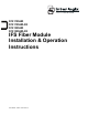
D19100SHR Series RS - 232 DATA (DCE MODE) RS - 232 DATA (DTE MODE) CONTROL LINES (DCE MODE) CONTROL LINES (DTE MODE) 1 2 3 4 5 6 7 8 20 1 2 3 4 5 6 7 8 20 DATA INPUT DATA OUTPUT GROUND DATA OUTPUT DATA INPUT GROUND 1 2 3 4 5 6 8 9 20 CHASSIS GRD 1 2 3 4 5 6 8 9 20 CHASSIS GRD RTS CTS DSR DCD DTR RTS CTS DSR DCD DTR
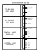
D19100SHR Series OTHER CONNECTIONS* * For further information see Appendix RS-422 DATA 9 10 11 12 13 21 22 MAY BE TEMPORARILY CONNECTED TO PIN 24 TO RESET ANTI-STREAMING "FAIL" CONTACT CLOSURE, NORMALLY CLOSED 23 24 CONNECT TO PIN 24 FOR MASTER CONTROL MODE SIGNAL GROUND 14 15 16 17 DATA IN + DATA IN DATA OUT + DATA OUT - 14 15 DATA IN / OUT + DATA IN / OUT- 14 15 16 17 DATA IN + DATA IN DATA OUT + DATA OUT - + 5 VOLTS JABBER RESET MASTER RELAY ACTIVE MODE CONTACT CLOSURE 2w RS-485 DATA 4w R
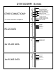
D19100SHR B A J K A B C L D M E N F G H P I Q R NOTE: WITHOUT PROPER FIBER CONNECTION, LED's DO NOT INDICATE CORRECT OPERATIONAL STATUS. O Receive A A: Optical Input LED illuminates when RTS is in active state.
Internal Jumper Settings D19100WDM Series #1 #2 B RS422 B A RS485 (2w) A B RS485 (4w) A A JABBER RTS LOD JMP 2 A B NOT USED USED JMP 3 #2 #1 RS232 B B A JMP 4 64 SEC 32 SEC 16 SEC 8 SEC 4 SEC JABBER TIME 64 SEC 32 SEC JMP 5 16 SEC 8 SEC LOD TIME
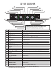
D19100SHR Series B A 1 2 Auto C Manual D A B C D E DCE DTE Master Slave E Power Connector Data / Control Lines Connector Auto / Manual Selector Switch DCT / DTE Selector Switch Master / Slave Selector Switch
D19100SHR Series 1 2 Auto Manual DCE DTE Master Slave MANUAL: Use this setting on all units in a single master configuration or on a slave unit. AUTO: Use this setting on a master unit in a redundant master configuration. All slave units should always be set to manual.
D19100SHR Series 1 2 Auto Manual DCE DTE Master Slave DCE: RS232 connections are configured as Data Communications Equipment DTE: RS232 connections are configured as Data Terminal Equipment
D19100SHR Series 1 2 Auto Manual DCE DTE Master Slave When Auto/Manual switch is set to Manual, sets master and slave units. In a single master configuration. When Auto/Manual switch is set to Auto, Master sets primary master, Slave sets redundant master.
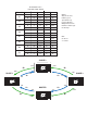
D19100SHR Series FAILURE LOGIC TABLE If break in: Loop LED Master A1 A2 A3 A4 B1 B2 B3 B4 Slave 1 Slave 2 Slave 3 A Y OFF Y Y B G G G G A Y G OFF Y B G G G G A Y G G OFF B G G G G A Y G G G B G G G G A G G G G B Y Y Y OFF A G G G G B Y Y OFF G A G G G G B Y OFF G G A G G G G B Y G G G NOTE: Grayed out areas indicate good operational loop in noted direction. Multiple fiber breaks follow the failure logic for that loop.
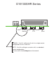
INSTALLATION INSTRUCTIONS FOR ADDITIONAL COMPONENTS NEEDED TO MEET EMISSION REQUIREMENTS ON THE D19100SHR SERIES PRODUCTS. INSTALL AS SHOWN. DB 25 DATA CABLE (CUSTOMER SUPPLIED) RADIO SHACK PART NO.
Appendix Automatic Switching Master The automatic switching master feature gives the Self Healing Ring the capability of having two redundant masters for the purpose of increasing fault tolerance Each master node may be connected to individual host computers, or to a single host computer using a simple Y connection. Master nodes may be located anywhere in the ring. In a redundant master configuration, one master will always be in active mode while the other in standby mode.
FCC Compliance This device complies with Part 15 of the FCC Rules. Operation is subject to the following two conditions: (1) This device may not cause harmful interference, and (2) this device must accept any interference received, including interference that may cause undesirable operation. Changes or modifications not expressly approved by International Fiber Systems, Inc. could void the user’s authority to operate the equipment.
Contacting us For help installing, operating, maintaining, and troubleshooting this product, refer to this document and any other documentation provided. If you still have questions, contact us during business hours (Monday through Friday, excluding holidays, between 5 a.m. and 5 p.m. Pacific Time). Sales and support contact information North America Toll-free: 855.286.8889 in the US, including Alaska and Hawaii; Puerto Rico; Canada. Outside the toll-free area: 503.885.5700.
Product Disassembly Instructions for WEEE Per European Directive 2002/95/EC Waste Electrical and Electronic Equipment Required Tools: One number 2 Phillips (crosstip) screwdriver. One number 2 flat screwdriver. For the enclosed box version: 1. Locate and remove box cover securement screws. Usually, but not limited to, at least 4 screws. 2. Lift off box top cover. 3. Locate and remove securement screws for printed circuit board. 4.
Copyright Trademarks and patents Manufacturer Certification ACMA compliance Canada European Union directives © 2011 UTC Fire & Security. All rights reserved. Interlogix and IFS names and logos are trademarks of UTC Fire & Security. Other trade names used in this document may be trademarks or registered trademarks of the manufacturers or vendors of the respective products. UTC Fire & Security Americas Corporation, Inc.