
Installation Instructions

Page
3
Assembly
B
2
A
2
6
3
2
1
3
5
1a
4
smooth
front side
structure
2
1
77
119
2a
1,100
1a
7
smooth
front side
structure
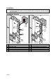
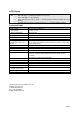
A Countersunk screws for fastening B Cylinder head screws for fastening
1 Reader housing 1 Reader housing
1a Connecting cable 1a Connecting cable
2 Mounting plate (smooth side at the front) 2 Mounting plate (smooth side at the front)
2a Cutout for connecting cable 2a Cutout for connecting cable
3 Housing cover 3 Housing cover
4 3x 25 countersunk bolts 6 Cylinder head screws
5 Single/double-gang back box 7 Dowel S 6
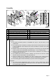
Please mind the following points when installing and connecting the reader:
Assembly
ð
The potted electronics permits an installation not only in a dry but also in a wet
environment.
ð
The mounting surface behind the proximity reader must be smooth and even in order
to prevent distortion when fastening the screws and allow the housing cover safely
lock into place.
ð
Besides common wall mounting, the arrangement of chamfering in the mounting plate
permits mounting into single/double-gang back boxes, e.g. into a DIN back box.
ð
Only use countersunk bolts which are flush with the chamfering, for fastening the
mounting plate (see Figure A).
ð
The cylinder-head screws enclosed in delivery can be used to mount the reader
housing and the mounting plate to the wall (Figure B).
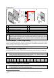
ð
Once the function test is completed, the cover is placed on the reader housing,
pushed to the back until the retaining pins and the mounting plate lock into place.
ð The mounting plate enclosed in delivery may also be used as boring pattern.
Connection
ð
An at least 10-wire shielded data cable, e.g. type J-Y-(ST) Y 5x2x0.6 mm, may be
used to extend the available connecting cable. In this case, GND and +5 VDC have to
be connected with 2 wires each.