
Installation Instructions

Proximity Reader P60-W01
Page
3
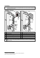
Assembly
1b
1a
1
B
80,3/ 3,16
68,8/ 2,7
40,8/ 1,6
42,4/ 1,66.
20,4/ 0,8
1b
A
1a
C
1100/
43,31
LED GN
LED RD
SHIELD
D 2/ CPS
D 1/ DATA1
D 0/ DATA0
BUZ
GND
+5 V DC
green
pink
black
grey
white
brown
yellow
blue
red
4
10
9
8
7
6
5
4
3
2
1
1
4
1
14
CPU
IC
REL K 1
REL K 2
S 1
J 6
4a
1
2
3
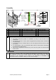
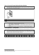
A Assembly B Connection to access manager C Drilling plan
1 Housing with MPU board 4 Access manager IF 0-610 1 Housing with MPU
1a Chamferings 4a Terminal strip Kl.3 in IF 0-610 1a Fastening bores
1b Connecting cable 1b 7 mm knockout for cable
2 Cover
3 Countersunk bolts
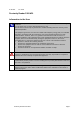
The following must be considered when the reader is installed:
1. The potted electronics permits an installation not only in dry but also in wet
environment.
2. The minimum distance to other systems equipped with proximity readers is limited to
0.3 meters/11.8”.
3. If mounted on metal, a minimal impact on the read range performance must be taken
into account.
4. To avoid distortion, only use countersunk bolts, which are flush with the chamfering,
for fastening the reader housing.
5. When having completed the function test, put on the cover, push it to the back until it
locks in place.
Connection
Connect the connecting cable to the terminal strip designated for this purpose. The colors of
the conductors as well as the relevant signals are shown above in Figure B. Further
information on the connection can be found in the “Instructions on Installation and
Connection” which is enclosed in delivery of each access manager.