
Installation Instructions

Page
4
Connection
A
2
1
1a
B
4
5
LED GN
LED RD
SHIELD
D 2/ CPS
D 1/ DATA1
D 0/ DATA0
BUZ
GND
+5 V DC
green
pink
black
grey
white
brown
yellow
blue
red
3
10
9
8
7
6
5
4
3
2
1
1
4
1
14
CPU
IC
REL K 1
REL K 2
S 1
J 6
3a
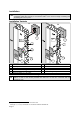
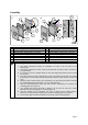
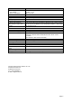
A Proximity reader connection B Presentation of an identification medium
1 Reader housing 4 Credential in check card format
1a Connecting cable 5 LED:display
2 Mounting plate
3 Access manager, e.g. IF 0-610
3a Terminal strip in IF-0-610
Connect the connecting cable (Figure A, 1a) to the terminal strip marked for this purpose in
the access manager (Figure A, 3). The colors of the conductors as well as the relevant
signals are shown in the above figure. Further information on the connection can be found in
the “Instructions on Installation and Connection” which is enclosed in delivery of the
respective access manager.
How to Correctly Present the Identification Medium
In order to permit a correct data capture, the identification medium must be presented within
the specified range and in parallel to the proximity reader until the red or green LED lights up
and a short “beep” can be heard (see figure).
LEDs
The LEDs signalize:
- Blue LED light => operational readiness of the reader
- Green LED light => a door opening
- Green LED light and a short “Beep” => positive booking response followed by a door
opening
- Red LED light and “Beeps” repeated at intervals => a negative booking response
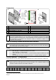
Access Manager - Configuration
Access managers are only able to read the transmitted data if the reader is defined as of HID/P type.
The reader type setting can be checked via the OC menu
1
$ cfg (see also “read1” of the table
below). Define the reader type via the OC menu $ termini –x (x = hardware address of the
terminal) if another reader type than HID/P is indicated.
$ cfg
No B A HA TNo type HWU SWU display keys read1 read 2 In/ Out
x x x x x IF 610 2.01 x - - Prox - -
1
The OC menus are part of the IF 1xxx software and can be invoked via the service interface of these systems.