
Installation Instructions

Page
3
Assembly
B
2
A
2
6
3
2
1
3
5
1a
4
smooth
front side
structure
2
1
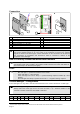
77/ 3.01
119/ 4.69
2a
1,100/
43.31
1a
7
smooth
front side
structure
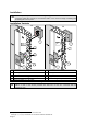
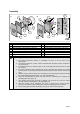
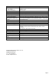
A Mounting into single/double gang back boxes B Fastening with dowels
1 Reader housing with reader board 1 Reader housing with reader board
1a Connecting cable 1a Connecting cable
2 Mounting plate (smooth side at the front) 2 Mounting plate (smooth side at the front)
2a Cutout for connecting cable 2a Cutout for connecting cable
3 Housing cover 3 Housing cover
4 3x 25 countersunk bolts 6 Cylinder head screws
5 Single/double-gang back box 7 Dowel, e.g. S6
The following must be considered when the reader is installed:
1. The potted electronics permits an installation not only in dry but also in wet
environment.
2. The minimum distance to other systems equipped with proximity readers is limited to
0.3 meters/11.8”.
3. If mounted on metal, a minimal impact on the read range performance must be taken
into account.
4. To prevent distortion when fastening the screws and allow the housing cover safely
lock into place, the mounting surface behind the proximity reader must be smooth and
even.
5. Besides common wall mounting, the chamfering in the mounting plate permit mounting
into single/double-gang back boxes, e.g. into a DIN back box.
6. Only use countersunk bolts which are flush with the chamfering, for fastening the
mounting plate (see Figure A).
7. The cylinder-head screws enclosed in delivery can be used to mount the reader
housing and the mounting plate to the wall (Figure B).
8. Once the function test is completed, the cover is placed on the reader housing,
pushed to the back until the retaining pins and the mounting plate lock into place.
9. The mounting plate enclosed in delivery may also be used as boring pattern.