
Installation Instructions

Page
2
Installation
Install the proximity reader next to the locking device in an unsecured area and connect the
connecting cable either directly or via extension cable
2
to the access manager controlling and
monitoring this access point.
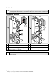
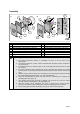
Installation Variants
2
1
3
A
B
1a
1
max.
100m
4
3
1
1a
max.
2m
4
A Connection via extension cable B Direct connection
1 Proximity reader 1 Proximity reader
1a Connecting cable 1a Connecting cable fed in an empty tube
2 Junction box
1
with 10-pin terminal strip 3 Empty tube, max. 2 m
3 10-wire, shielded cable
2
in empty tube 4 Access manager or junction box
4 Access manager, e.g. IF 0-610
An at least 10-wire, shielded data cable
2
may be used to extend the available connecting
cable to a lenth of 100 meters provided that GND and +5 VDC are connected with two
conductors each.
1
The junction box may also be installed in the secured area.
2
Cable type: e.g. J-Y (ST) Y 5x2x0,6mm or 10 conductor shielded cable AWG 22.