
User Manual
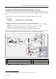
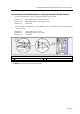

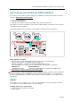
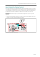
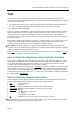
Table Of Contents

Technical Manual for Master Terminals of the Series IF 152x
Page 25
Connection of Surveillance Sensor, Opening Contact/ Handle Contact
# Connect the surveillance sensor to the input/ output connector board.
Terminal 1 to IN 1 signal cable to surveillance sensor
Terminal 3 to GND signal cable to surveillance sensor.
Terminal 4 to line shield
# Connect the door opening button or the handle contact to terminal strip 2 of the input/ output
connector board:
Terminal 2 to IN 2 signal cable to contact
Terminal 3 to GND signal cable to the contact
Terminal 4 to line shield
2
IN 2
IN 1
sensor cable
shield
button
1
cable length
max. 25 m
4
shield
terminal
strip
Kl. 2
connection
3
2
1
2
IN 2
GND 0V
circuit
terminal
strip Kl. 2
BE
3
4
IN 1
REL 2
REL 1
REL 3
Br. 1
8
Br. 3
Br. 4
J 2
1
2
3
4
1a
1
Graph: Connection of surveillance sensor and door opening button to input/ output connector board
1 Input/ output connector board 2 Connection of floating sensors
1a Terminal strip Kl.2
# Caution: Secure all cables with a strain relief.