
User manual


harDware
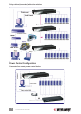
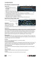
Front Panel (compressed view)
Status LEDs
• Selected identies a port with a
green light.
• Live identies an on-line port with
a red light.
• Bank No. identies this particular
switch within a daisy-chain conguration.
• 10/100 lights solid orange when the current digital link runs at 100 Mbps.
• Link lights solid green when a network link is established; it ashes whenever network
transmissions are perceived on the digital port.
• Power lights solid red to indicate the power is on.
• Video blinks orange to indicate the normal functioning of the video server.
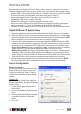
Rear Panel (compressed view)
Serial Port 1
Connect the serial console
cable for advanced console
management of the switch
via a serial terminal emulation utility, such as Windows HyperTerminal or Linux/Unix Minicom.
Serial Port 2
Connect to either an external modem or a power control unit (or to a cascaded chain of power
control units). When an external modem is added to its serial control port (RJ12), the switch can
serve either as a PPP server to allow direct cable connection or dial-in connection from its
peer computers, or as a PPP client to dial out to an ISP or Enterprise PPP server. Furthermore,
through serial commands sent over its serial control port, the switch can perform remote
power on/off and power cycling tasks via the (cascaded) power control module(s).
Ethernet Port
This digital port (RJ45) offers anytime/anywhere access to the Digital KVM over IP Switch and,
subsequently, the conventional KVM switch(es) and servers/computers connected behind it to
the remote login clients over the LAN/Internet.
PC Ports
Connect to your computer(s) using 3-in-1 connection cable(s).
Restore-to-Default Button
Located to the left of the power jack, it’s accessed by using a pointed object, such as a pin. To
restore the switch to factory defaults (the IP settings and user account settings established
before you do any of your own congurations), press the button for 5 seconds or more.
Power Adapter Jack
Use only the 9 V DC external power adapter included with the switch to avoid nullifying the
warranty.
Daisy Chain Out
Connect to additional switches for daisy-chained (cascaded) congurations.
Console
Connect the keyboard, mouse and monitor for the local console.
8
HARDWARE
Port-switching buttons (8-port model shown)
Link
Video
10/100
Selected
Live
Bank no.
Power
Serial port 2 (serial power control/external modem support)
Serial port 1 (console management)
Restore-
to-default
button
Power adapter jack
Ethernet port PC ports (8-port model shown)
Daisy chain out
Local console ports: keyboard, video, mouse