
Instructions


2
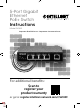
Connections & Indicators
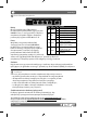
LEDs
The LED indicators make it easier to
monitor the switch and its connections.
NOTE: Ports 1 – 4 can provide power
to a connected powered device,
and all powered devices should
comply with IEEE 802.3at/af.
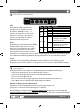
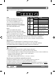
Ports
All RJ45 ports on the switch support
Auto-MDI/MDI-X functionality, so
you can use straight or crossover
UTP/STP cables to connect
the RJ45 ports to PCs, routers, hubs, other switches, etc. Cat5e/6 UTP/STP
cables provide optimal performance; if a status LED doesn’t indicate a link or
activity, check the corresponding device for proper setup and operation.
Power
Use the included power cord and adapter to connect the device (on the rear
panel) to an AC outlet. Confirm that the PWR LED on the front panel is lit.
Installation
Prior to use, it is recommended that the switch be placed/positioned:
• on a level surface that can support the weight of the switch
• with at least 25 mm (approx. 1”) of clearance for ventilation;
• away from sources of electrical noise: radios, transmitters, broadband amplifiers, etc.;
• within 100 m (approx. 328’) of network devices it’s to be connected to.
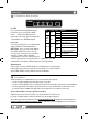
Chassis Ground Column (Rear Panel)
Wire the grounding terminal to an earth grounding object to
protect equipment from external electrical surges.
For specifications, visit intellinetnetwork.com. Register your product at register.
intellinet-network.com/r/561839 or scan the QR code on the cover.
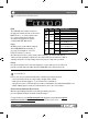
LED Color Status Status Description
PWR Green
Off Power Off
On Power On
Link/
ACT
Yellow
Off No link establlished.
On Valid port connection.
Flashing Sending or receiving data.
Speed Green
On
A device is connected to the
port at 1000 Mbps speeds.
Off
A device is connected to the
port at 10/100 Mbps speeds.
PoE Green
Off No PD is connected to the port.
On
The connected device
is receiving power.
Instructions
English