Gigabit Web-Smart Switch user manual Models 524063 & 524087 Shown: Model 524063, 24-Port INT-524063/524087-UM-0308-02
Thank you for purchasing the INTELLINET NETWORK SOLUTIONS™ Gigabit Web-Smart Switch, Model 524063 (24-Port) or Model 524087 (16-Port). This handy device lets you increase the speed of your network with 10/100/1000 Mbps auto-sensing ports that automatically detect optimal network speeds, and it lets you increase the speed of your own work through user-friendly Web-based management for uncomplicated administration.
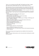
Contents hardware installation...............................................................................5 web-based browser management..........................................................6 Switch Access..................................................................................................6 Configuration....................................................................................................7 System...........................................................................
safety & compliance statements Federal Communications Commission (FCC) Statement This equipment has been tested and found to comply with the limits for a Class A digital device, pursuant to part 15 of the FCC Rules. These limits are designed to provide reasonable protection against harmful interference when the equipment is operated in a commercial environment.
hardware installation Selecting a Site for the Switch As with any electrical device, you should place the switch where it will not be subjected to extreme temperatures, humidity or electromagnetic interference. Specifically, the site you select should meet the following requirements: • The ambient temperature should be between 32 and 104 degrees Fahrenheit (0 to 40 degrees Celsius). • The relative humidity should be less than 90 percent, non-condensing.
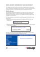
web-based browser management The Gigabit Web-Smart Switch switch provides an Administration Authority that lets you configure and manage the switch remotely. This section describes how to configure the switch using its Web-based browser management interface. Switch Access The advanced management capabilities of the switch can be accessed using a standard Internet browser.
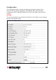
Configuration The Configuration menu includes the following subsections: System, Ports, PVLANs, 802.1Q VLANs, Aggregation, MAC Binding, ARL Table, Multicast Configuration, RSTP, Mirroring, Quality of Service, Filter, Rate Limit and Storm Control. System This screen provides the current status of the device. Click “Apply” so any changes that are made will take effect.
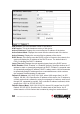
S/W Version: This is the software version of this device. H/W Version: This is the hardware version of this device. Active IP Address: Displays the current effective IP address of the device. Active Subnet Mask: Displays the current effective subnet mask of the device. Active Gateway: Displays the current effective gateway of the device. DHCP Server: If the device uses the DHCP server to connect to the network, the system will display the IP address of the DHCP server. The default value is 0.0.0.
through 255, separated by periods. Typically, subnet mask numbers use either 0 or 255 as values (e.g., 255.255.255.0), but other numbers can appear. Fallback Gateway: XXX.XXX.XXX.XXX, where XXX ranges from 0 to 255. Default: 192.168.1.1. Specifies the default gateway IP address. It is only required if you intend to manage the device from another LAN connected via an IP router. The gateway address must be on the same IP subnet as this device.
Default: 0.0.0.0. This is the IP address of the user’s SNMP management station if it is configured to receive traps and notifications. SNMP Read Community: Any 20 characters. Default: public. This parameter identifies the MIB tree(s) to which this entry authorizes read access. SNMP Write Community: Any 20 characters. Default: private. This parameter identifies the MIB tree(s) to which this entry authorizes write access. SNMP Trap Community: Any 20 characters. Default: public.
Link: Displays the current link status of each port: “1000MFDX,” “100MFDX,” “100MHDX,” “10MFDX,” “10MHDX” or “Down.” The field lights green and shows the link speed if there is a valid connection on the port. Mode: Options are “Auto speed,” “10M/Half,” “10M/Full,” “100M/Half,” “100M/Full,” “1000M/Full” and “Disabled.” Default: Auto. Enabling .
VLAN Configuration List: Options range from “VLAN Group 1” to ““VLAN Group 24” (default). Specifies the VLAN Group No. to configure its members. VLAN Members: Options range from “Port 1” to “Port 24” and “Trunk 01” to “Trunk 08” (default: none selected). These are ports that are allowed to be members of the VLAN. A trunk can be selected as a VLAN member, but a trunk group needs to be configured first.
Egress rules are the rules applied to all frames when they are transmitted by the switch, as indicated below. From here, you can configure the IEEE 802.1Q tag-based VLAN members. You need to configure the current VLAN mode on the System Configuration screen to be 802.1Q VLAN. VLAN List: Options range from “1” (default) to “4094.” Specifies the VLAN ID to configure its members. First you need to click “Add” to add your VLAN ID.
VLAN Members: Options range from “1” to “24” and “Trunk 01” to “Trunk 08” (default: none selected). These are ports that are allowed to be members of the VLAN. A trunk can be selected as a VLAN member, but a trunk .group needs to be configured first. Delete: Click to delete the current VLAN Group configuration. Modify: Click to complete the current VLAN configuration. When your VLAN Mode option is 802.1Q tag-based VLAN, you need to configure the VLAN member port’s attribute.
VLAN Aware: Either “Enabled” or “Disabled” (default). When enabled, the VLANaware attribute will be enabled; when disabled, the VLAN-unaware attribute will be enabled. The native operation mode for an IEEE 802.1Q-compliant switch is VLAN-aware. Even if a specific network architecture doesn’t use VLANs, the system default VLAN settings allow the switch to still operate in a VLAN-aware mode while providing functionality required for almost any network application. However, the IEEE 802.
Group: Options range from “Group1” to “Group 8” or “Normal” (default). NOTE: The trunk group number doesn’t affect port trunk operation in any way and is only used for identification. The port of the normal group does not belong to any trunk groups. Port: Select any combination of numbers valid for this parameter (default: none selected). This creates a list of ports aggregated in the trunk. Procedure Recommendations and Limitations Link aggregation is also known as port trunking or port bundling.
3. Double-check the port trunk configuration on both switches. 4. Reconnect or re-enable the ports. If the port trunk is being configured while the ports are still connected or enabled, the ports will be disabled for a few seconds automatically. Also, consider these function limitations when configuring port trunks: • A port mirroring target port can not be a member of a port trunk. However, a port mirroring source port can be. • A DHCP relay agent client port can not be a member of a port trunk.
arl table This screen allows you to view MAC addresses of the MAC address table. MAC Address: XX-XX-XX-XX-XX-XX, where XX ranges 0 to FF. Default: 00-0000-00-00-00. Specifies the MAC address to search for. Search: Click to start searching for the specified MAC address. Note: The MAC address table consists of static addresses, dynamic addresses and the device address.
A consumer may join any number of multicast groups, issuing a membership report for each group. Hosts on the segment note membership reports from other hosts and will suppress their own reports accordingly. In this way, the IGMP protocol guarantees the segment will issue only one join for each group. The router periodically queries each of its segments in order to determine if at least one consumer still subscribes to a given stream.
only to forward multicast traffic. When the querier election process is complete, the switch simply relays IGMP queries received from the querier. When sending IGMP packets, the switch uses its own IP address, if it has one, or an address of 0.0.0.0, if it doesn’t have any assigned IP address (e.g., when sending packets on a non-management VLAN).
rstp The Gigabit Web-Smart Switch provides these RSTP-related features: • Industry-standard support of the Rapid Spanning Tree Protocol, which features a compatibility mode with legacy STP. • Superior performance, as RSTP will recognize a link failure and put an alternate port into forwarding mode within milliseconds. • RSTP may be enabled on a per-port basis. • Ports may be configured as edge ports, which allows rapid transitioning to the forwarding state for non-STP hosts.
• While providing a much better performance than STP, IEEE 802.1w RSTP still .. . required up to a few seconds to restore network connectivity when a topology change occurred. A revised and highly optimized RSTP version (which this switch supports) was defined in the IEEE standard 802.1D-2004 edition and now reduces network recovery times to just milliseconds. RSTP States and Roles RSTP bridges have roles to play, being either root or designated.
frame transfer. In a network of RSTP bridges, the time spent in this state is usually quite short. RSTP bridges operating in STP compatibility mode will spend 6 to 40 seconds in this state. After learning, the bridge will place the port in the forwarding state. The port both learns addresses and participates in frame transfer while in this state. From here, you can configure the RSTP. System Priority: Options range from “0” to “61440.” Default: 32768.
Spanning Tree Protocol to support: Normal only supports Rapid Spanning Tree Protocol; Compatible supports both STP (802.1d) and RSTP. Protocol Enabled: Either “Enabled” or “Disabled” (default). Enabled means you’re enabling RSTP for this port as per the configuration in the RSTP Port Configuration menu. STP may be disabled for the port only if the port does not attach to an STP-enabled bridge in any way. Failure to meet this requirement will result in an undetectable traffic loop in the network.
the port is to leave STP enabled but to configure the port as an edge port. A good candidate for disabling STP would be a port that services a single host computer. You can enable RSTP of all aggregations. Edge Port: Either “Enabled” (default) or “Disabled.” Edge ports are ports that do not participate in the Spanning Tree, but still send configuration messages. Edge ports transition directly to frame forwarding without any listening and learning delays.
port, the traffic stream of valid frames on any source port is made available for analysis. Select a target port that has a higher speed than the source port. Mirroring a 1000Mbps port onto a 100Mbps port may result in an improperly mirrored stream. Frames will be dropped if the full duplex rate of frames on the source port exceeds the transmission speed of the target port.
Prioritize Traffic: Options are “Custom” (default), “All Low Priority,” “All Normal Priority,” “All Medium Priority” and “All High Priority.” This screen allows you to quickly configure the 802.1p priorities. 802.1p Value: Ranging from 0 to 7, these are the values of the IEEE 802.1p priority. Priority: Options are “low,” “normal,” “medium” and “high.” Default: according to the Priority Traffic option. This is a QoS assigned to received tagged frames with the specified IEEE 802.1p priority value.
Prioritize Traffic: Options are “Custom,” “All Low Priority,” “All Normal Priority,” “All Medium Priority” and “All High Priority” (default). This screen allows you to quickly configure the DSCP priorities. DSCP Value: Enter a value from 0 to 63. This is a Differentiated Services Code Point (DSCP) – a value of the 6-bit DiffServ field in the Type-of-Service (ToS) field of the IP header. Priority: Options are “low,” “normal,” “medium” and “high.” Default: according to the Priority Traffic option.
Prioritize Traffic: Options are “Custom,” “All Low Priority” (default), “All Normal Priority,” “All Medium Priority” and “All High Priority.” This screen allows you to quickly configure the Port priorities. Priority: Options are “low,” “normal,” “medium” and “high.” Default: according to the Priority Traffic option. Specifies the default QoS priority for each port.
filter Mode: Options are “Disabled” (default), “Static” and “DHCP.” Specifies the source IP address filter model. Disabled allows all packets to be forwarded; Static allows packets with the specified source IP address to be forwarded while other packets are discarded; DHCP allows packets with a DHCP server assigned as the source IP address to be forwarded. IP Address: XXX.XXX.XXX.XXX where XXX ranges from 0 to 255. Default: 0.0.0.0. Specifies the packets’ source IP address to be allowed forwarding.
subnet mask is a 32-bit number that is notated by using four numbers from 0 through 255, separated by periods. Typically, subnet mask numbers use either 0 or 255 as values (e.g., 255.255.255.0), but other numbers can appear. DHCP Server Allowed: Either “Enabled” or “Disabled” (default). When the DHCP option is configured, enable these parameters; otherwise, the DHCP packets will be discarded and the port will discard all packets.
Policer: Options range from “128” to “3698 Kbps” or “None” (default). This is the rate at which received frames will start to be discarded by the switch. Shaper: Options range from “128” to “3698 Kbps” or “None” (default). This is the maximum rate at which the switch will transmit frames on this port. The switch will discard frames in order to meet this rate, if required.
Monitoring Detailed Statistics View the detailed transmitting and receiving status of each port by clicking the port’s hyperlink. Click “Clear” to clear all statistics; click “Refresh” to renew them.
Receive Total Panel Rx Packets: The number of received good packets (Unicast+Multicast+Broadcast) and dropped packets. Rx Octets: The number of octets in received good packets (Unicast+Multicast+ Broadcast) and dropped packets. Rx High Priority Packets: The number of received High Priority good packets and dropped packets. Rx Low Priority Packets: The number of received Low Priority good packets and dropped packets. Rx Broadcast: The number of good Broadcast packets received.
Receive Error Counters Panel Rx CRC/Aligment: The number of packets received which meet all the following conditions: • Packet data length is between 64 and 1518 octets inclusive. • Packet has invalid CRC. • Collision Event has not been detected. • Late Collision Event has been detected. Rx Undersize: The number of received packets that meet all the following conditions: • Packet data length is less than 64 octets. • Collision Event has not been detected. • Late Collision Event has not been detected.
Port: Any combination of numbers — corresponding to port numbers as seen on the switch’s front panel — valid for this parameter. VLAN ID: Displays a value from 1 to 4094 or “None” (default). Path Cost: Displays a value from 0 to 2147483647 or “None” (default). This is the cost offered by this port. If the Bridge RSTP cost style is STP, 1Gbps ports will contribute 4, 100Mbps ports will contribute 19 and 10Mbps contribute a cost of 100.
is automatically turned off in situations where multiple STP brdges communicate over a shared (non-point-to-point) LAN. The bridge will automatically take pointto-point to be true when the link is found to be operating full duplex. The pointto-point parameter allows this behavior or operates a point-to-point link, but cannot run the link full duplex. It will force the parameter false when the port operates the link full duplex, but is still not point-to-point (e.g.
software upload Browse... Browse...: Click to find the new firmware file you want, then click “Upload” to upgrade the firmware and reboot the switch system. IMPORTANT: During the upgrade process, don’t turn off the power or any function on the Web page. logout Click to exit the Web management interface. console management The Gigabit Web-Smart Switch switch provides a console interface for local configuration through its RS232 port.
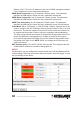
Note: The super password can’t be modified; and only one console user can log on to the switch at a time. Command-Line Interface (CLI) Commands The console management interface is based on command lines. After you log in to the system, the root directory displays. Enter “?” to show all commands. If you’re not sure about the correctness of a command entry, enter “?” or a space and the system will list possible commands and descriptions, as shown on the screen below.
Enter the IP address, IP mask, IP gateway or VID according to the above format. help This displays command syntax information.
System Configuration System Restore Default System Reboot console management 41
IP Configuration IP Setup IP Ping 42 console management
specifications Standards • IEEE 802.1d (Spanning Tree Protocol) • IEEE 802.1p (Traffic Prioritization) • IEEE 802.1q (VLAN Tagging) • IEEE 802.3 (10Base-T Ethernet) • IEEE 802.3u (100Base-TX Fast Ethernet) • IEEE 802.3ab (Twisted Pair Gigabit Ethernet) • IEEE 802.3ad (Link Aggregation) • IEEE 802.
INTELLINET NETWORK SOLUTIONS™ offers a complete line of active and passive networking products. Ask your local computer dealer for more information or visit www.intellinet-network.com. Copyright © INTELLINET NETWORK SOLUTIONS All products mentioned are trademarks or registered trademarks of their respective owners.