
User manual


FRONT PANEL
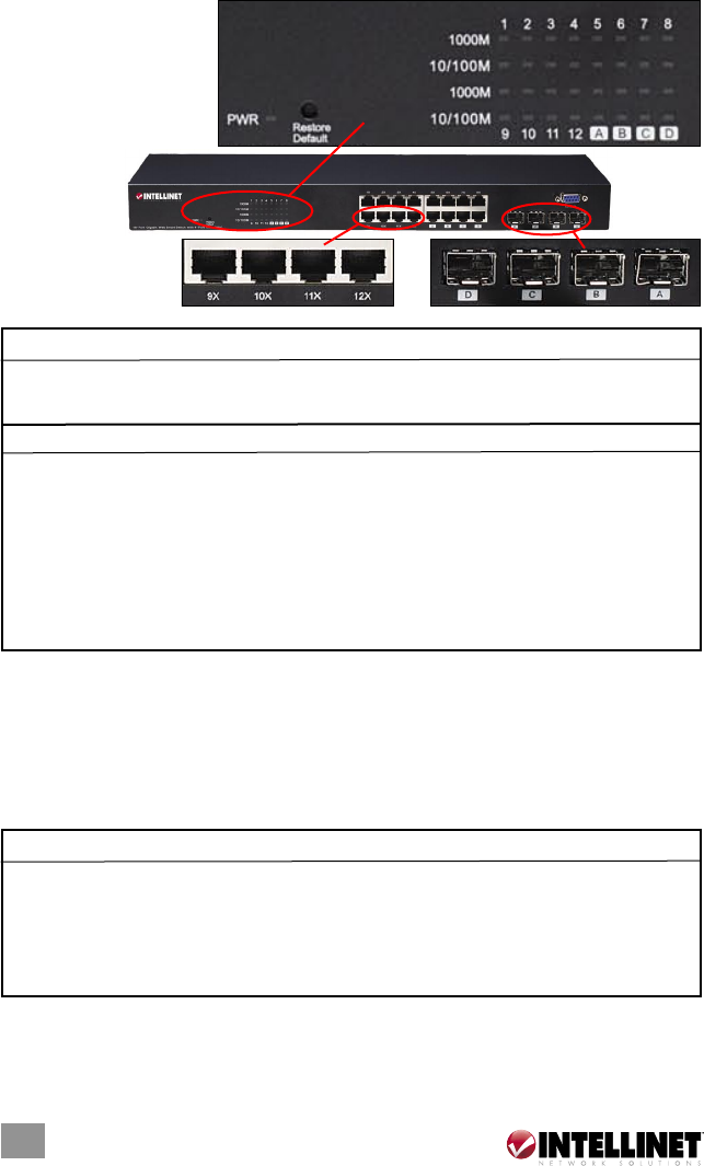
Ports and LED indicators
are found on the front
panel of the switch. The
tables below explain
their purpose and
operation.
LEDs
NOTE: The four mini-GBIC slots (A, B, C and D) share LED indicators with the
last four RJ-45 (copper) ports (i.e., ports 13–16 on the 16-port model and ports
21–24 on the 24-port model).
Ports
The auto-negotiation feature allows ports to operate in one of the following modes:
NOTE: For the last four (highest numbered) ports, when both the fiber (mini-
GBIC) and copper (RJ-45) interfaces are connected, the switch automatically
disables the copper port and activates the fiber interface.
4
INTRODUCTION
System LED Status Operation
PWR Steady green Power on
Off Power off
Port LEDs Status Operation
1000M Steady green Valid port connection at 1000 Mbps
Blinking green Valid port connection; data being transmitted/
received
Off No valid link or connected at 10/100 Mbps
10/100M Steady green Valid port connection at 10/100 Mbps
Blinking green Valid port connection; data being transmitted/
received
Off No valid link or connected at 1000 Mbps
Media Speed Duplex Mode
10/100/1000 Mbps copper 10 Mbps Half/Full Duplex
100 Mbps Half/Full Duplex
1000 Mbps Full Duplex
1000 Mbps (fiber – mini-GBIC 1000 Mbps Full Duplex
required)
16-port
model
shown