NSC18-WN Pan/Tilt Network Camera user manual Model 550857 INT-550857-UM-0709-01
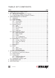
table of contents section page 1 COMPONENTS & CONNECTIONS.................................................................. 6 2 SOFTWARE INSTALLATION............................................................................ 8 2.1 Locating the IP Address of the Camera.................................................... 8 2.2 Using the Admin Utility to Locate the Camera..........................................11 3 WEB MANAGEMENT INTERFACE.............................................................
introduction Thank you for purchasing the INTELLINET NETWORK SOLUTIONS™ NSC18-WN Pan/Tilt Network Camera, Model 550857. Ideal for home-network-based video streaming, this camera is simple to set up and operate, so you can soon be enjoying the benefits of these popular features: • 1.
regulatory statements EU Declaration of Conformity This device complies with the essential requirements of the R&TTE Directive 1999/5/EC. This device is a 2.4 GHz wideband transmission system (transceiver) intended for use in all EU member states and EFTA countries, except in France and Italy, where restrictive use applies.
FCC Caution Any changes or modifications not expressly approved by the party responsible for compliance could void the user’s authority to operate this equipment. IEEE 802.11b or 802.11g operation of this product in the U.S. is firmwarelimited to channels 1 through 11. FCC Radiation Exposure Statement This equipment complies with FCC radiation exposure limits set forth for an uncontrolled environment. This equipment should be installed and operated with a minimum distance of 20 cm (approximately 8 in.
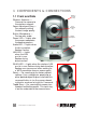
1 components & connections 1.1 Front and Side Wireless Antennas — Connect the camera to the wireless network. Focus Adjustment Ring — For manually setting the best image quality. Built-in Microphone — For two-way audio. Power LED — Lights after the camera completes the booting process. Audio LED — Lights when Audio is enabled; flashes if active. LAN LED — Lights when the LAN port is in use; flashes during data transfers.
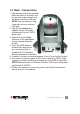
1.2 Back / Connections 1. Connect one end of the included Ethernet cable (or a similar one) to your local area network and the other end to the LAN port. NOTE: You can skip this step if you plan to use a wireless LAN only. 2. Plug the included power adapter into an A/C outlet and connect it to the 12VDC power jack. 3. Attach the two included antennas to the connectors (shown already attached at right). 4.
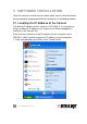
2 software installation Once the camera connections have been made, launch Internet Explorer on your computer and proceed with the instructions in the following sections. 2.1 Locating the IP Address of the Camera The default IP address of this camera is 192.168.2.3. If you prefer to assign a different IP address to it, log on to the Web management interface of the camera first. If the first three sections of the IP address of your computer aren’t 192.168.
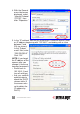
2. Double-click the Network Connections icon. 3. Right-click on the Local Area Connection icon, then click “Properties” from the menu that displays.
4. With the General menu tab/screen displayed, select “Internet Protocol (TCP/IP),” then click “Properties.” 5. In the “IP address” field on the subsequent Properties screen, enter an IP address beginning with “192.168.2” and ending with a value between 2 and 254 (as shown). In the “Subnet mask” field, enter “255.255.255.0.” Click “OK.” NOTE: If you forget the IP address of the camera after you change it, there are two ways to recover it: • Reset back to 192.168.2.
2.2 Using the Admin Utility to Locate the Camera If you can’t connect to the camera using the above procedure, you can use the admin utility software to search for cameras connected to your local area network. Insert the included software CD, and it will automatically begin to install the admin utility. NOTE: If it doesn’t auto-start, go to Start on your desktop, then My Computer; double-click on the CD drive where the software CD is located, and double-click the “Setup_Admin_3.0.1” icon, as shown below.
2. When the Select Destination Location screen displays, click “Next” to use the default installation folder and continue, or click “Browse” to select an existing folder or drive to install the admin utility. 3. When the Select Additional Tasks screen displays, you may select the “Create a desktop icon” and “Create a Quick Launch icon” options, then click “Next” to continue.
4. When the Ready to Install screen displays (presenting all the selected options), click “Install” to continue or “Back” to make more changes. 5. When the Completing the IPCam Admin Utility Setup Wizard screen displays, click “Finish” to complete the install. NOTE: The “Launch IPCam Admin Utility” option should be selected by default.
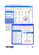
After the camera’s admin utility is launched, all cameras found on your local area network will be displayed with basic information. To connect to a certain camera using your Web browser, double-click the camera listed. This initial screen also introduces the Language drop-down menu (above the camera-list field) and the three icons at the bottom (from left to right): Search Camera; Browse Camera via Web; and Configure Camera.
DHCP — Select to set the camera to automatically obtain an IP address from the DHCP server on the local area network. Manual IP — Select to input the IP address information manually. Click “OK” to save the settings.
On the Security screen (above), you can change the camera’s name and password (as on the Login screen, the username is always “admin” and can’t be changed). Be sure you enter the same password in both the “New Password” and “Confirm Password” fields; otherwise, you’ll be prompted to enter the new password again. Click “OK” to save the settings; click “Cancel” to discard changes. 3 web management interface 3.1 Logging On With new camera purchases, there should be no problem with the login/ logon procedures.
3. The NSC18-WN Pan/Tilt Network Camera requires a special ActiveX control (plug-in) in order to work properly. Right-click on the message in the address bar to display an options menu (right), then click “Install ActiveX Control...” to continue. 4. When the Security Warning screen displays (below), click “Install.” You should now be able to view live images on the Camera screen (see 3.2 Camera Settings below).
Pan/Tilt Speed — This specifies the moving speed when you use the Pan/Tilt function to point the camera in a different direction. Options are “1” (fastest) to “5” (slowest). The faster the speed, the less precise the control of the movement. Resolution — Options for the video resolution are “1024 x 768,” “640 x 480” and “320 x 240” @ MPEG4; or “1280 x 1024,” “640 x 480” and “320 x 240” @ MJPG.
field of view, select a lower image quality to get a higher image refresh rate. Video Type — Select the video encoding type: “MJPEG” or “MPEG4.” Frame Rate — The highest image refresh rate of this camera is 30 (the same as a TV). However, if you are using an Internet connection with limited bandwidth and you don’t need a fast image refresh rate, you can limit the maximum refresh rate (frame rate). Options are “30,” “15,” “10,” “5” and “3.
saved image file (the default filename is the current date and time). The default directory used to save image file is “C:\”; but you can change by clicking the text field to the right of “Snapshot” and entering a new directory. Recording — Click to record the displaying image as a video file in AVI format. You can play back the video file using Windows Media Player. To stop recording, click “Stop Recording” (the same button). As with “Snapshot,” you can change the directory used to save the file.
Click in this area, for example, to aim the camera lower. 3. When the camera is in the position you want, enter a descriptive name in the “Position Name” field and click “Set to Point n” (where “n” is the number of the memory slot) to save the position. Once it’s saved, the position can be instantly recalled from the Camera menu by clicking the position number on the Preset Points panel.
Add — Click to add a new guard tour (see below for detailed steps.) Edit — Click to modify the settings of a configured tour. Start/Stop — Click to activate a selected guard tour; click again to stop it. Once a tour has begun, go to the Camera menu screen to view the images. NOTE: Only one tour can be active at a time. Remove — Click to delete a selected tour from the list. Adding a Guard Tour Click “Add” to display the Set Up Guard Tour screen below.
View Order — Assign this position a number greater than 1 and different from the other positions. Unless Random Order is selected, each tour will start “visiting” positions in order, from 1 to the highest configured number and then back to 1. Remove — Click to delete a selected position from the list. Save — Click to save the settings. Close — Click to close the window and discard all changes not saved. 3.
Network Type — Select “DHCP” to obtain an IP address automatically or “Static IP Address” to assign the camera a fixed IP address. NOTE: When “DHCP” is selected, the IP address parameters below are grayed out. IP Address / Subnet Mask / Gateway — Enter the appropriate settings. Primary DNS — Enter the IP address of the DNS server. If you don’t know it, ask a network administrator or your ISP for help.
Available Networks — This is a list of all wireless access points found by the camera. Not all access points will be displayed at the same time, so if the AP you expected to connect to doesn’t appear you may need to click “Refresh” several times until it does. • Connect: Select a device you want to connect to. • SSID: Unless a wireless AP’s SSID is hidden (meaning you’ll need to identify the device by its MAC address), it’ll display here.
you want to connect to. If the wireless access point does not use encryption, “Disabled” will be displayed here. • Network Type: Displays either “Infrastructure” or “Ad Hoc.” SSID — Enter the SSID of the wireless access point you want to connect to. It should be fewer than 32 alphanumerical characters. When you select a wireless access point from the Available Networks list, its SSID will be displayed in .this field automatically unless it’s hidden, in which case you won’t be able to connect to it.
Enable DDNS — Select “Enable” to activate the function; “Disable” to deactivate it. Provider — dyndns.org is currently the only option available. Host Name — Enter a dynamic DNS hostname. User Name — Enter a dynamic DNS username (the same used for the dyndns.org account). Password — Enter a dynamic DNS password (the same used for the dyndns.org account). Apply — Click to put any of the above settings/changes into effect. 3.4.
You can double-click the icon to launch Internet Explorer and directly log on to the camera’s Web management interface. 3.4.5 LoginFree LoginFree is a function that allows unauthorized users to view images captured by the camera. It also lets you integrate images with your own Web applications. Filename — Enter a filename and click “Apply” to save the settings. Other users can now access the image by this filename with a “.jpg” extension and the camera’s IP address as the prefix.
/ 3.5 Motion Detection Settings This function is another useful security tool, as it takes a snapshot when there’s movement in the image area being monitored. With five subsections as shown below, all motion detection-related settings can be configured on this menu’s screens. 3.5.1 Motion Detection Enable Motion Detection — Select “Enable” to activate the function; “Disable” to deactivate it. Motion Detection Interval — From the drop-down menu, select the time interval (in seconds) between two motions.
Sending File Type — Select the file type that’ll be saved when motion is detected. Select “JPEG” and a still picture in JPEG format will be saved; select “AVI” to save a video clip. Send snapshot file to FTP — Select “Enable” to send the saved file to the designated FTP server when motion is detected; select “Disable” to disable the function. NOTE: You need to configure the FTP server parameters first (see 3.5.4 FTP Configuration below).
Refresh — If the object or objects in the image captured by the camera move off screen, click to reload the image so you can re-define the motion detection region (see below). Save — Click to save your settings. You can re-size and re-position a region with your mouse just as you would any other image. • Click and hold the mouse button after you mouse-over one of the eight perimeter points that define the region, then drag the mouse to re-size the region.
3.5.3 E-Mail As mentioned in 3.5.1 Motion Detection, these settings need to be entered before you can take advantage of the “Send snapshot file to E-Mail” option. Recipient E-Mail Address — Enter the address files are to be sent to. E-Mail Subject — Enter something that will indicate the desired level of importance or urgency to the recipient. SMTP Server — Enter the IP address or hostname of the SMTP server (the server that delivers your e-mail). If you don’t know it, refer to your e-mail software (e.g.
3.5.4 FTP Configuration As mentioned in 3.5.1 Motion Detection, these settings need to be entered before you can use the “Send snapshot file to FTP” option. FTP Server — Enter the IP address or hostname of the FTP server. FTP Port — Enter the port number of the FTP server. User Name — Enter the FTP server username. Password — Enter the FTP server password. Remote Folder — Enter a remote folder name to be used on the FTP server.
3.6 System Info With four subsections as shown below, all operations-related settings can be configured on this menu’s screens. System Info Camera Information Date/Time Setting Utilities Status 3.6.1 Camera Information This screen lets you set the camera’s name and administrator’s password. Camera Name — Enter an easily recognizable name for each configured camera on the network so its purpose is clear.
Set Date/Time manually — Enter the date in the first three boxes, then the time. The format for the date is YYYY/MM/DD (so that July 2, 2012 = 2012/07/02); the 24-hour format for the time is HH:MM:SS (so that 9:24:30 pm = 21:24:30). NTP Server — Select to input the date and time automatically from the NTP server. Time Zone — Select the appropriate time zone from the drop-down menu. NTP Server — Enter the IP address or hostname of the NTP server. You can use the default value “pool.ntp.
if it responds slowly or erratically. LED Setting — Click “Turn off LED light” if you don’t want anyone in the view field of the camera to be able to tell that the camera is activated. Click the button again to switch the LEDs back on. 3.6.4 Status This screen provides information about the camera you may need for reference. NOTE: “Video Port” and “HTTP Port” correspond to “AV Control Port” and “Web Port,” respectively, in 3.4.1 Network Settings/ LAN. 3.
Configure the settings for these user-level accounts on the Account screen. Login — Enter a login username. Password — Enter a password for this user. Confirm password — Re-enter the password. Add — Click to add this user account to the network. When a user is added, it will display in the table above the “Apply” button. NOTE: However many users are enabled, only one (including the administrator) can view the camera image at a time. Yes/No — Select to enable or .disable this user account.
3.8 SDHC With three subsections as shown below, this screen presents options for SD-HC (secure digital – high capacity) card-related operations. SDHC Status Space Alarm File Management 3.8.1 Status This screen displays remaining card space for storing image files. 3.8.2 Space Alarm When you’re using an SD card to store captured images and video clips, you can configure the camera to send an e-mail to you when you’ve reached the limit of reserved space left on the card.
SMTP Authentication — Select “Enable” if the SMTP server you’re using requires authentication, then enter the username and password below; select “Disable” if the server doesn’t require authentication. If you’re not sure, ask your ISP or network administrator. Reserved Space — From the drop-down menu, select the amount of SD card space that will be reserved and not used. Apply — Click to put any of the above settings/changes into effect.
Start on your desktop, then My Computer; double-click on the CD drive where the software CD is located, and double-click the “Setup_ Viewer_3.0.0.6” icon, as shown above. 2. When the Welcome to the IPCam Surveillance Software Setup Wizard screen displays, note the recommendation that all other applications be closed before proceeding, then click “Next.” 3.
4. When the Select Additional Tasks screen displays, select “Create a desktop icon” and/or “Create a Quick Launch icon” as desired, then click “Next.” 5. When the Ready to Install screen displays, showing the settings selected on previous screens, click “Install” to begin the installation procedure or “Back” to change/modify any of the settings. A status screen will display (Installing) to show the progress of the install.
6. When the Completing the IPCam Surveillance Software Setup Wizard screen displays, click “Finish” and the Viewer will be activated. If you prefer to activate it later, de-select “Launch IPCam Surveillance Software” before clicking “Finish.” 4.2 Viewer Controls The Viewer can be activated by clicking its desktop/quick-launch icon or by selecting “IPCam Surveillance Software” from the Start menu’s Internet Camera folder.
Video display area display layout 1 2 4 3 11 12 message display box 7 8 9 10 6 5 selected camera. Press to quit Full Screen mode. Scan (2) — Click to automatically cycle through the views from all connected cameras. Click once to activate the function (the icon turns blue); click again to stop scanning (the icon turns white).
position. NOTE: This function is available only with cameras that feature it. Record (7) — Click to begin video recording from a selected camera. The start date and time of the recording is confirmed in the Message Display Box; for example, “7/2 11:23:00, Camera 4 Start Manual” (started manually). Likewise, the message “7/2 11:25:00, Camera 4 Stop Manual” would indicate the recording was manually stopped two minutes later. Configure (8) — Click to configure the camera(s) on the network. (See 4.
4.3 Configuration Before you can effectively use the Viewer program and all its features, all cameras connected to the network need to be configured. Click the Configure button on the Viewer control screen to display the “Configure Cameras”/“General Options” menu, and select “Configure Cameras.” NOTE: If you’re prompted by a Windows security alert asking you if you want to block the “IPCamViewer” program, click “Unblock”; otherwise, the Viewer program will not be able to function properly. 4.3.
Channel — Select the channel number you want to set. Camera Search — All cameras found on your local network will be displayed in this window. Select — With a camera highlighted in the Camera Search window, click “Select” to fill in the Camera Configuration text fields in the panel above with that camera’s parameters. Refresh — If the camera you expected to see doesn’t appear in the Camera Search window (including any camera[s] connected to your network since the last scan), click to rescan and re-display.
4.3.1.2 Schedule Recording Channel — Select the channel number you want to set. One Time Schedules — This window displays recording schedules you set for specific cameras that will be executed only once. New / One Time Schedules — Click to display a new One Time Schedule screen for the .selected camera. Enter/select “To” and “From” dates/times, then click “OK” to save the settings or click “Cancel” to undo any changes.
New / Weekly Schedules — Click to display a new Weekly Schedule screen for the selected camera. Select applicable days of the week; enter/select a “From” time; then set the duration of the video recording in the “Period” field (HH:MM:SS format). The end time of the recording will be calculated automatically and displayed in the “To” field. Alternatively, click “All Time Record” to record the full 24-hour period (12:00:00 AM to 11:59:59 PM) of every day.
Channel — Select the channel number you want to set. Mute Audio — Select if the designated camera does support audio but you prefer not to hear it. Record Video Only — Select if the designated camera does support audio but you prefer not to record it along with any video recordings. OK — Click to save the current settings. Cancel — Click to cancel any .changes you’ve made before saving. 4.3.1.
4.3.2 General Options When you click the Configure button on the Viewer control screen and select “General Options” from the resultant popup menu (4.3 Configuration), the four submenus detailed below will display, presenting system-wide settings options for the Viewer. 4.3.2.1 General Data Directory — Enter a directory (folder) for storing video and images. To select a directory already on your hard drive, click “Browse.” Free Recording Space — Remaining storage space (MB) is displayed here.
Scan Time — Enter/select an amount of time (in seconds) the Viewer will display the view from each camera when the Scan funtion is enabled (see 4.2 Viewer Controls). Cycle Recording — Select an option for times when the hard disk runs out of space: “Enable” means recorded video files will be overwritten; “Disable” means they won’t be. OK — Click to save the current settings. Cancel — Click to cancel any .changes you’ve made before saving. 4.3.2.
E-Mail Subject — Enter the subject of the e-mails being sent. Recipient E-Mail Address(es) — This window displays a list of the e-mail addresses established for notification. New — Click to add an e-mail address for notification. Enter the address in the text field on the subsequent screen (right), then click “OK.
time you attempt to open the Viewer as long as this feature is enabled. (The Authentication Required screen at right will display: Enter the password and click “OK” to access the Viewer / surveillance software.) Enable — Password authentication is required to access the program. Disable — No password authentication is required to access the program. Password — Enter the password you want to use. Confirm Password — Enter the password you want to use again. 4.3.2.
4.4 Changing the Display Layout The Viewer features eight different display layouts for up to 16 cameras, with each layout presenting a unique arrangement and number of cameras. Just click the image of the layout you want (as shown below) and the video display area will change to that layout. Layout style 1: 1 Camera only Displays the video of 1 camera only. Layout style 2: 4 Cameras Displays the video of up to 4 cameras.
Layout style 4: 8 Cameras Displays the video of up to 8 cameras. 01 02 03 04 05 Layout style 5: 9 Cameras Layout style 6: 10 Cameras 06 07 08 Displays the video of up to 16 9 cameras. 01 02 03 04 05 06 07 08 09 Displays the video of up to 10 cameras.
Layout style 7: 13 Cameras Layout style 8: 16 Cameras 56 SURVEILLANCE SOFTWARE Displays the video of up to 13 cameras. 01 02 03 04 05 06 07 08 09 10 11 12 13 Displays the video of up to 16 cameras.
5 troubleshooting Should the camera not function as expected, see if the problem — along with possible solutions — is listed below. Can’t connect to the camera. • Confirm the IP address setting of the computer you’re using. If it’s not in the same subnet as the camera, they won’t be able to communicate with each other. • Make sure the IP address you used to connect to the IP camera is correct. • If you forget the IP address of the camera, you need to reset it to the factory default value (192.168.2.
• Unplug the power adapter from the wall socket and plug it in again after 10 seconds, then try to connect to the camera again. • If the camera is correctly powered (the Power LED is on) but you still can’t connect to it when you’re sure the IP address is correct, contact your dealer for help. The camera is set to send an image by e-mail or to an FTP site, but nothing is received. • If the image is sent by e-mail, make sure it’s not blocked by any antispam mechanism.
6 specifications Standards • IEEE 802.11b (11 Mbps Wireless LAN) • IEEE 802.11g (54 Mbps Wireless LAN) • IEEE 802.11n Draft 2.0 (300 Mbps Wireless LAN) • IEEE 802.3 (10Base-T Ethernet) • IEEE 802.3u (100Base-TX Fast Ethernet) General • 32-bit ARM9 RISC CPU • DSP: Prolific PL-1029 • 4 MByte flash memory • 32 MByte SDRAM • Supported image resolutions: - MPEG4: 1024 x 768, 640 x 480 and 320 x 240 - Motion=JPEG: 1280 x 1024, 640 x 480 and 320 x 240 • Video frame rate: max.
INTELLINET NETWORK SOLUTIONS™ offers a complete line of active and passive networking products. Ask your local computer dealer for more information or visit www.intellinet-network.com. Copyright © INTELLINET NETWORK SOLUTIONS All products mentioned are trademarks or registered trademarks of their respective owners.