Table of Contents SAFETY AND REGULATORY NOTICES .....................................................3 1: PRODUCT OVERVIEW.........................................................................6 1.1 NETWORK CAMERAS ............................................................................ 6 1.2 NETWORK VIDEO SERVERS .................................................................... 7 1.3 MODEL OVERVIEW ..............................................................................
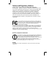
Safety and Regulatory Notices Thank you for purchasing this INTELLINET NETWORK SOLUTIONS™ Network Camera or Network Video Server. This user manual includes instructions for using and managing the camera on your network. Experience in networking will be helpful when setting up and using this product. Updated versions of this document will be posted to www.intellinetnetwork.com as they become available.
Waste Electrical & Electronic Equipment Disposal of Electric and Electronic Equipment (Applicable in the European Union and other European countries with separate collection systems) This symbol on the product or its packaging indicates that this product shall not be treated as household waste. Instead, it should be taken to an applicable collection point for the recycling of electrical and electronic equipment.
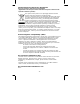
Important Information 1. Camera surveillance laws may differ for each country. Contact the local authorities to avoid any surveillance law violations. 2. Note that the image sensor of this network camera can be damaged permanently if exposed to direct sunlight. Defective image sensors that have been damaged by prolonged exposure to direct sunlight are excluded from the product warranty. 3. Indoor network cameras are not weatherproof.
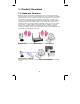
1: Product Overview 1.1 Network Cameras Network cameras are closed-circuit television (CCTV) cameras that use the Internet Protocol (TCP/IP) to transmit image data over an Ethernet or Wireless LAN connection. As such, network cameras are also referred to as IP cameras. IP cameras are primarily used for surveillance applications. A number of IP cameras are normally deployed together with a digital video recorder (DVR) or a network video recorder (NVR) to form a video surveillance system.
1.2 Network Video Servers A network video server allows connection to an analog CCTV camera via coaxial cable. Example showing a CCTV camera connected to a network video server, which itself is connected to the network. 1.3 Model Overview This user manual contains information for the following models: 1. NSC15/NSC15-WG Motion-JPEG + MPEG4, Audio, 300k CMOS NSC15-WG only: Day/Night, 54 Mbps Wireless 802.11g 2. NSC16-WG Motion-JPEG + MPEG4 + H.264, Audio, 1.3M CMOS, Day/Night, 54 Mbps Wireless 802.11g 3.
5. NFC31/NFC31-WG Motion-JPEG + MPEG4 + H.264, Audio, 1.3M CMOS NFC31-WG only: 54 Mbps Wireless 802.11g IEEE 802.3af PoE Support for wired model NFC31. 6. NFC31-IR/NFC31-IRWG Motion-JPEG + MPEG4 + H.264, Audio, 1.3M CMOS, Day/Night, IR LEDs NFC31-IRWG only: 54 Mbps Wireless 802.11g IEEE 802.3af PoE Support for wired model NFC31-IR. 7. NFD30 Motion-JPEG + MPEG4, Audio, 300k CMOS, IEEE 802.3af PoE Support 8. NBC30-IR Motion-JPEG + MPEG4, Audio, 300k CMOS, Day/Night, IR LEDs, IEEE 802.3af PoE Support 9.
2: System Requirements 2.1 Hardware Requirements Your computer hardware should meet or exceed the following specifications: Access to a single camera with Web browser: CPU: Pentium 4 1600 MHz (or equivalent AMD) Video Card: 64 MB graphic card RAM: 512 MB Network Adapter: 10/100 Mbps Fast Ethernet Using the 16-Channel viewing / recording utility: CPU: INTEL Dual Core Processor Video Card: 64 MB graphic card RAM: 2 GB OS: Windows XP, Windows Vista or Windows 7 2.
2.3 Limitations Web Browser Access While it is possible to connect to the network camera with a Web browser other than MS Internet Explorer, some of the features cannot be used. Refer to the overview below: MS Internet Explorer 7.x and 8.
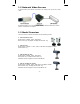
3: Hardware Overview 3.1 Front & Rear The following pages provide an overview of the hardware features of the different types of network cameras and the network video server. 3.1.1 NSC15/NSC15-WG/NSC16-WG Network SOHO Cameras Front The image above shows the options for the wireless models NSC15/16-WG. The wireless antenna connector and the Night-Vision LEDs are exclusive to these models and cannot be found on the wired model NSC15.
Rear Power Connector: The connection for the power adapter, which is supplied with the camera. Reset Switch: If you need to perform a hardware reset, you can insert a paper clip into the reset hole and depress the switch for 10 seconds. Speaker: Stereo connector for the connection of active speakers or other line-out audio sources. LAN: Connection for standard RJ45 Cat5 (or better) network cable. Maximum length is 100 m / 300 ft.
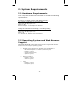
3.1.2 NFC30/NFC31 Network Fixed Cameras Front Top Mounting Point 1/3” CS-Mount Lens Bottom Mounting Point Camera Stand Front IR Versions The IR cameras are equipped with a fixed lens that cannot be removed or replaced. The IR lens features 12 IR LEDs that output a wavelength of 850 nm and allow the camera to capture video in complete darkness.
Rear Microphone / Line-In Connector: Connector for external microphones or other line-in audio sources. Wireless Antenna Connector: RP-SMA jack for the connection of external antennas, such as the one provided with your wireless camera. Digital I/O Connector: Terminal block adapter for the connection of external alarm devices. The connector has two inputs and two outputs. Connection using IEEE 802.3af Power over Ethernet Note: Connection using the power adapter is supported as well.
3.1.3 NFD30 Network Dome Camera Power Connector: For connection of 12 V DC input. Audio Out (Green Line): To support audio out with earphones or speakers for two-way audio. To support audio in for microphone. Audio In (Red Line): Network Connector: For the connection to the RJ45 Ethernet cable. The connector supports IEEE802.3af-compliant PoE input signals. Network Indicator: Indicates that the camera has successfully connected to the network.
1: Connection using IEEE 802.3af Power over Ethernet. 2. Connection using a standard power adapter (1) and a regular LAN switch or router (2).
3.1.
1: Connection using IEEE 802.3af Power over Ethernet. 2. Connection using a standard 12 V DC power adapter (1) and a regular LAN switch or router (2). The power adapter is not included.
3.1.5 NVS30 Network Video Server Front Video In: Input connector for analog CCTV camera. Video Out: Loop-through port that outputs analog video, which can be integrated into an existing CCTV surveillance system. Mic In: Microphone/Line-In input connector. Line Out: Line-Out connector for active speakers. I/O Terminal Connector: 1 Input and 1 Output to support External Alarm and Sensor devices used for motion detection, event triggering and alarm notification.
Rear PWR: LED lights up once the network video server has successfully started up. Power Connector: Connect the power adapter here, unless you wish to utilize the Power over Ethernet functionality. Network / PoE Connector: Standard RJ45 socket for Cat5 (or better) network cable. IEEE 802.3af-compatible input sources are supported. Connection Diagram Note: The NVS30 is a one-channel video server. Only one CCTV camera can be connected at a time.
3.2 Digital I/O Terminal Block Connector The Network Camera and Network Video Server, with the exception of the NSC15 models, are equipped with a digital I/O interface. It can be used to connect external alarm sensors (pins 1 and 2) or to power external devices (pins 3 and 4). From left to right: Pins 1 (DI+), 2 (DI-), 3 (Com) and 4 (No) NO COM DI- DI+ Ground Switch 12 V Alarm out device Ground 12 V Max.
3.3 Package Contents You should find the following items in the packaging of your INTELLINET NETWORK SOLUTIONS video surveillance product. 1. Network Camera (or Network Video Server) 2. User manual (this document) and Quick Installation Guide 3. Installation CD -> User Manual in electronic form in different languages -> IP Installer Utility -> Multi-Channel IP Surveillance Utility 4. Camera stand (all indoor NSCxx and NFCxx models) 5. Wall-Mount bracket (all outdoor NBCxx models) 6.
4: Installation 4.1 Connecting to the Camera Connect the RJ45 network cable from the camera’s LAN port to your network; e.g., the router or a LAN switch, then power on the camera. The boot sequence will take about one minute. You will need to use the camera’s power adapter, unless your camera supports PoE (see section 1.3 Model Overview). In that case you can connect the RJ45 cable to a PoE enabled switch or injector to power the camera.
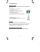
4.1.1 Windows XP, Vista and Windows 7 Insert the Installation CD into the CD or DVD-Drive. After a few moments, the CD will automatically start and display the screen below. If that does not happen, you need to browse the CD with Windows Explorer and double-click the autorun.exe file. 1. User Manuals The user manual for the INTELLINET NETWORK SOLUTIONS Network Camera is available in electronic form on the installation CD, along with user manuals in different languages.
IP Installer for Windows Installation Before you start with the installation, make sure that you are connected to your computer with a user account that has administrator rights. The screen shots below are taken from an installation on a Windows XP system. The procedure on Vista and Windows 7 systems is similar. To begin the installation, click on the link “IP Installer for Windows.” After that, depending on your system’s settings, you may see the message shown below.
Specify the location where the program should be installed. The default path is OK to be used on most systems. Click on “Browse…” to select a different location and click on “Next” to continue. Select the Windows Start Menu folder. Select or de-select the optional Xvid Codec and MSN Plugin. If you are not sure about these options, it is recommended to keep them selected. Click “Next” to continue.
Verify the installation summary and click “Install” to begin the installation. Once the installation has completed, click on “Finish”. A new shortcut has been created on your computer desktop; Double-click it to start the application.
IP Installer for Windows When the program starts, you are presented with the screen shown below. Depending on your camera model, the screen may look slightly different, but the functionality is the same. The IP Installer utility lists all cameras that can be found on your network. With this utility you can make changes to the configuration, perform a firmware upgrade, restore the camera to factory default values, and reboot the camera.
Setup: Select a camera from the list and click the Setup button in order to open the camera configuration dialog. Upgrade: Select a camera from the list and click the Upgrade button if you wish to upgrade the firmware of the camera. The firmware upgrade can also be performed with your Web browser. Factory default: If you want to reset the camera settings to factory default values, you can select a camera from the device list and click this button.
User Account Settings Page User Name: Enter the user name you wish to use for the new account. Password: Enter the password for the new user account. Confirm: Type the password in again. Mode: There are three possible values to choose from: 1. Admin: User has full access to all camera functions. 2. Operator: User can view the live image and change image related settings such as brightness, contrast, etc. 3.
Date/Time Settings Page The network camera is equipped with an internal clock. You can display the current date and time information on the video, so that when you look at recorded video material or images you can easily tell when the recording was made. Before you can use this function, you need to define how the camera obtains the time. Current Setting: Displays the current date and time. PC clock: Displays the time of the PC that you are using right now.
Network Settings Page The default configuration is shown above, and for most users there should be no need to change these settings. Advanced users can change the following values: HTTP Port: This is the Web server port of the camera. The default value is 80. You can change the value from 80 to a value between 1024 and 65535. Note that when you change the HTTP port, you need to append the new port to the address of the camera; e.g., http://192.168.0.102:1024.
PPPoE Settings Page This page allows defining of the PPPoE settings of the camera. This function is not required for the vast majority of users, and if you are not planning on connecting the camera directly to a DSL modem (no network present, just the camera connects directly to the modem) you can safely skip this page. PPPoE is a common connection method for ADSL Internet services. It is not required for cable modem service, or newer DSL services that operate with dynamic IP addresses.
DDNS Settings Page DDNS stands for “Dynamic DNS.” DDNS is useful for all users who have an Internet service with a dynamic IP address. Most DSL services utilize IP addresses that are highly dynamic and change as often as once every 24 hours. Cable modem services typically keep the IP address assigned to a user for a longer period of time; e.g., up to 30 days.
Language Settings Page The INTELLINET NETWORK SOLUTIONS network camera provides a multilanguage user interface for Web-browser access. In order to use this function, you first need to install the additional languages by uploading them to the camera. The default language is English. Additional languages can be found on the Installation CD, or you can download them from the INTELLINET NETWORK SOLUTIONS Web site at www.networkipcamera.com.
Apply Settings Page This is the last page of the Setup. All configuration changes you have made on the previous screens will be saved when you click the Apply button. If you have selected an additional language to be installed on the previous page, clicking Apply will install that language as well. After you click Apply, the main screen of IP Installer shows up, and after a period of 60 to 180 seconds, the camera will show up in the UPnP device list.
5. 6. 7. 8. Will the battery in my notebook last for at least another 10 minutes? Am I connected to the camera with an RJ45 cable (not wireless)? Is the camera I want to upgrade located in my local network? Am I sure about what I am doing? If you answer any of these questions with “no,” you should not perform the firmware upgrade and skip this section. Select a network camera from the UPnP device list and click on Upgrade to upgrade the firmware.
User tab This screen offers two functions: 1. You can change the individual settings of the camera in a similar fashion as with the Setup function on the main screen. However, instead of clicking on Previous and Next to switch between the screens, you can access the individual options more quickly by clicking on any of the tabs (User, Date/Time, TCP/IP, PPPoE and DDNS). You cannot install additional languages with this function, however. 2.
About tab This screen displays the version number and date of the IP Installer utility. If you need to contact the INTELLINET NETWORK SOLUTIONS Technical Support, make sure that you obtain the information from this page and include it in your message to Technical Support. Accessing the camera Select the camera from the UPnP device list and then click on Link to IE. MS Internet Explorer will open the camera page automatically.
When you connect to the INTELLINET NETWORK SOLUTIONS network camera for the first time with MS Internet Explorer, you need to install an ActiveX control. The following message appears: Click on Install to being the installation. Depending on your system, additional messages may appear; e.g., the Web browser notification bar. In any event, you need to allow the installation of the ActiveX control.
4.1.2 MacOS The installation on Apple systems running MacOS X does not involve the INTELLINET installation CD. The INTELLINET NETWORK SOLUTIONS network camera supports Apple’s Bonjour service. Bonjour, formerly Rendezvous, is Apple Inc.'s trade name for its implementation of Zeroconf, a service discovery protocol.
The Network Camera is shown in the category Webpages. In order to connect to the camera, double-click the circled link. Safari then connects to the camera and the message below appears: Click on Allow and you will see the camera live image a few moments later. Refer to Chapter 5 for explanations on the Web interface options of your network camera.
4.1.3 Linux The installation on Linux systems does not require any special software. The network camera is compatible to Web browsers such as Firefox and Konqueror. The initial installation requires the setup of the camera’s IP address. As the camera by default obtains an IP address from a DHCP server in the network (e.g., a router), you can access the camera as soon as you have obtained the IP address from the router’s DHCP client log.
5: Web Browser Interface 5.1 Live Video Page Date/Time Stamp Snapshot/Full Screen (1) (2) (3) Audio Controls Video Controls Digital Zoom (1): This link opens the Settings page of the network camera. This is the administrator area that only users with admin user rights have access to. Refer to Chapter 5.2 for detailed information on the administrator settings. (2): In order to change any of the client settings, you need to have at least operator user rights on the camera.
View size: You can define the size of the live video by selecting the value of your choice. Depending on the camera model and settings, you may select values such as 320x240, 640x480, 2x, 1x, 1/2x, 1/4x. Protocol: Select from any of these protocols: HTTP, TCP, UDP. The default value is HTTP, and normally there is no reason to change it. Video buffer: Turn the Video Buffer function On or Off.
Digital Zoom: The digital zoom function allows magnification of certain areas of the video. After you click on the magnification icon, a window appears as an overlay on top of the image. See below. You can drag the box over the image, and you can adjust the magnification by moving the slider toward “T” (tele-zoom) or “W” (wide-angle). The more you move the slider toward “T,” the further you zoom in and details appear larger.
Snapshot: Use this button to take a snapshot of the video. When you click the button, a window opens showing the capture frame. You can then save the image by clicking on the Save button. Full Screen: Click this button to view the video in full screen mode. In full screen mode, the video is stretched to fit the entire screen and all control graphics and window elements are no longer displayed. To return from full screen mode, press the ESC key on your keyboard.
5.2 Settings Page (Administrator Menu) The camera’s administrator menu consists of two main options. Basic: The camera’s network, image and security settings are configured here. Advanced: Motion detection, event triggers, e-mail and FTP uploads can be configured here. 5.2.1 Settings Page – Basic Settings The basic link reveals the subsections “System,” “Camera,” “Network” and “Security.
Date/Time: In order to display the date and time stamp on the live video, or to utilize its scheduler, the camera is equipped with an internal time clock. There are several ways to set up the camera time. Note: Depending on your camera model and firmware version, the Daylight Saving Time option may not be available. Current date/time: Displays the camera’s current date/time. PC clock: This is the date and time of the computer you are currently using to connect to the camera.
become inaccurate as time passes and you will need to re-synchronize the time periodically. “Synchronize with NTP”: This option is the recommended setting. In this mode, the camera will synchronize its time settings based on the interval setting (ranging from once per hour to once per day). The camera obtains the time from the NTP server (default: pool.ntp.org).
Backup setting data: This function allows saving the current configuration of the camera to a file on your computer’s hard drive. Saving the configuration is useful in case you ever want to reload a specific configuration; e.g., in order to set up another camera of the same model and firmware version with the exact same configuration.
Another message will appear: Click on Cancel to abort the operation. Click on OK to start the upgrade process. You will see the following messages: Note: You may see additional messages at this stage. When you see this message, the upgrade has been completed. It may take up to two minutes to re-gain access to the camera. If the camera no longer responds, use the Windows IP Installer utility to find the camera and re-configure the IP Address settings.
Camera: This section contains the video-related settings of the camera. Depending on the camera model, the options may vary. There are two different styles, each of which has slightly different options. First you need to identify which style applies to your camera. Style 1: The main options are: - General - MPEG4 Computer View Mobile View - MJPEG Style 2: The camera section contains the subsections “General,” “H.264,” “MPEG4,” “MJPEG,” “3GPP,” “Advance” and “Playback.” This style applies to all H.264 1.
Camera -> General (Style 1): RTSP: RTSP stands for Real Time Streaming Protocol. RTSP is supported by most media clients, such as Real Player, VLC and QuickTime. If you only plan to view the camera video with your Web browser or with one of the provided software utilities, you do not need to activate this option. Note that activating the RTSP option disables the camera’s ability to send out Motion-JPEG video.
IR: Cameras that are equipped with infrared allow the control of the camera’s function at night. On: Activates the night vision mode. The IR cut filter is removed when this option is enabled. The IR LEDs are activated and the image turns black and white. Off: The IR functionality is deactivated and the camera will always send color images. At night, however, the camera will not be able to capture proper video.
When privacy masking is activated, a new option appears on the screen that allows you to censor (black out) an area in the image you don’t wish the camera to capture. Use your mouse in order to resize the box and move it into the desired position on the live video. Privacy masking is an important function designed to protect the people’s right for privacy. Example 1: The camera is installed in your home: e.g., overlooking your driveway.
Camera -> MPEG4 -> Computer View (Style 1): The RTSP and RTP options are for advanced users only. If you are not familiar with any of these terms, including Multicast and Unicast, there is a good chance that you do not need these functions of the camera. RTSP: This is only shown if the RTSP mode is enabled in the general settings. When activated, you can define which port you wish to use for the RTSP protocol. The standard port is 554, but you can use a different port, if desired.
Once you activate the multicast option, the screen will show additional options: Enter the address of your multicast server along with the audio and video port. The Time-To-Live value defines how long multicast traffic will expand across routers. Routers have a TTL threshold assigned and only datagrams with a TTL greater than the interface's threshold are forwarded. Below are additional details regarding the differences between Unicast and Multicast.
MPEG4 Viewer Port: The camera uses two ports, one for regular connections and one for SSL (HTTPS) encrypted connections. If you are using the INTELLINET NETWORK SOLUTIONS network camera only in your local network and do not wish to access the video remotely over an Internet connection, these values are unimportant. For remote connections, however, they are important. The ports entered here need to be programmed into your router’s port forwarding table to allow incoming remote connections.
Camera -> MPEG4 -> Mobile View (Style 1): The network camera has the ability to send out a low-resolution video stream that is ideal for remote viewing via a mobile phone. The camera supports 3GPP and 2.5 WAP for older phones. The options are the same as the computer view, except that the image size is fixed to 160x120 pixels, and the frame rate and quality settings are much lower. Camera -> MJPEG (Style 1): In addition to MPEG4, the network camera can also send out a Motion-JPEG video stream.
Camera -> General (Style 2): RTSP: Specify the RTSP port here. The default port is 554. RTP: Define the RTP port range here. Image Rotated: Choose from one of the following options: “None,” “Mirror,” “Flip” and “Mirror + Flip.” With this function you can mirror the image vertically, horizontally or both. The default value is “None.” Audio Codec: Here you can define which audio codec the camera uses. There are four choices: g.711 u-law / g.711 a-law: G.
Video Clip Format: The camera has the ability to send out short video clips to an FTP server, via e-mail or to a local SMB network storage device. Find more about that in the advanced section. Here you define the format of the video clip. You can choose between H.264 and MPEG4. Each of these streams can be defined individually in terms of video resolution and quality in the corresponding menus.
Camera -> H.264/MPEG4/MJPEG (Style 2): The network camera is a multi-stream device. It can send out H.264, MPEG4 and Motion-JPEG video. Each stream can be configured independently concerning video resolution, video quality and more. The individual setup pages have the same parameters. Viewer authentication: When activated, a user name and password is required in order to access the video stream. Multicast streaming: Enable this option to utilize multicast streaming.
Quality: This allows you to control the image quality of the video. Auto: The camera automatically adjusts the quality based on the connection speed of the connected client. Fixed quality: Select the quality from medium to excellent. Fixed bitrate: Define the maximum network bandwidth for this stream from 64 kbps (low quality) to 6 Mbps (high quality). Note: Fixed bitrate is not available for the MJPEG stream. IP Interval: This parameter defines the I-Frame interval.
Camera -> Advance (Style 2): White Balance: Select the value that best represents the installation environment of the camera, or leave it on auto to let the camera do the adjustment automatically for you. Lighting: If the camera is installed indoors, select either 50 or 60 Hz, depending on the power grid frequency in your country. Select Outdoor, if the camera is installed outside, or pointing outside.
Camera -> Playback (Style 2): The INTELLINET NETWORK SOLUTIONS Network Camera is equipped with an integrated video player. With this player you can play back videos that you have recorded with the camera; e.g., by using the record function on the live video page. The video player can also playback other video sources, if the necessary video codecs are installed on your computer. The controls consist of the typical array of buttons you find in most common media players; e.g.
Camera -> Network -> Information: On this page you can define the network settings of the camera. By default the camera is set up to automatically obtain the necessary IP information from the DHCP server (e.g., the router) in your network. You can, however, set up the IP address and related settings manually. MAC address: MAC address stands for Media Access Control address. This is the unique hardware address of the camera’s network interface.
Camera -> Network -> PPPoE: PPPoE is the most common form of connection for DSL-based Internet service. You can use this function to connect the camera directly to a DSL modem. A common application for this is where the network camera is installed in a remote location where no network is present. In the location is a DSL Internet connection (DSL modem), but no router or any other network infrastructure. You can connect the camera to the DSL modem and enter your DSL account information in the fields below.
Camera -> Network -> DDNS: If you are not planning on connecting to the network camera over a remote connection, but only in your local network, you can skip this section. Dynamic DNS is a network service that provides the capability for a networked device, such as a router or computer system, to notify a domain name server to change, in real time (ad-hoc) the active DNS configuration of its configured host names, addresses or other information stored in DNS.
Note: If the router in your home network is equipped with a DDNS client, we recommend using the router instead of the camera. Most SOHO routers are equipped with a DDNS client and since the router is in direct control of handling the Internet connection, it’s the device best suited for the DDNS task. Server Name: Select the DDNS provider of your choice. In our example we use www.dyndns.org. User ID: Enter the same user name here that you use to log in to your account settings on www.dyndns.org.
Camera -> Network -> UPnP: UPnP stands for Universal Plug and Play. A UPnP-enabled device, such as your network camera, announces its presence in the local network to other computers that support UPnP as well. The operating systems Windows XP, Windows Vista and Windows 7 support UPnP.
Camera -> Network -> Bonjour: Bonjour is a service that, just like UPnP, helps to find the network camera on the network. Bonjour is available for Windows, but is more commonly used for MacOS. Refer to section “4.1.2 MacOS” for additional information on the usage. Bonjour: On: Enables the service (on by default). Off: Disables the service. Device name: Enter the name of your camera here. This is the name the Bonjour service will display.
Notify type: Select which type of connection (DHCP, Static IP or PPPoE) should be observed by the IP notification function. For example, if you uncheck Static IP and your camera is set up with a static IP address, you will not receive an e-mail notification. SMTP server name: Enter the domain name of the Sendmail server (outgoing email server) here. SMTP server port: Port 25 is the standard port for SMTP connections. If your SMTP server uses a different port, you can enter it here.
Camera -> Network -> Wireless: If your network camera supports wireless, you can configure the related settings on this page. The camera has the ability to find the wireless network and allows you to quickly enter the correct encryption key. Status of wireless networks: All wireless networks in range are shown here. Select the correct wireless network by highlighting it. Once selected, you will see that some of the fields automatically populate.
Passphrase: Enter the password for your wireless network here. Repeat the password in the field below. The wireless interface has its own IP settings. These are independent from the regular settings (Network -> Information) and must be configured separately. Obtain an IP address automatically (DHCP): Enable this and the camera will obtain the IP information from the DHCP server in your network.
In order to use the function, you need to perform two steps. First, you need to set up a new account for the Windows Live / Hotmail service. This account will be used by your network camera. You cannot use your existing Messenger account for the camera. Note the user name and password for the new account and proceed to the configuration of the network camera. Login Account: Enter the user name of the newly created account here. Password: The password of the new account goes here.
Privacy: Set this to “On” to only allow people in the allow list to be able to connect to the camera and view the video. User: In order to add a user to the allow list, type in the user’s email address here and click on “Add.” If you wish to remove a user from the allow list, select the user from the allow list field below, then click Remove. Allow list: All users that can access the camera via Live Messenger are listed here.
Camera -> Security -> Account: The INTELLINET NETWORK SOLUTIONS network camera allows the creation of different user accounts with different levels of access to the camera. There are three main user levels. The Viewer account only allows viewing the live video page of the camera. The Operator account allows viewing the live video as well as changing the image setup settings, such as brightness, contrast, etc. Only the Administrator account has full access to all camera settings, including the Settings menu.
Camera -> Security -> HTTPS: Secure Sockets Layer (SSL) is a cryptographic protocol that provides security for communications over networks such as the Internet. HTTPS is a URI scheme used to indicate a secure HTTP connection (SSL encrypted). It is syntactically similar to the http:// scheme that is normally used for accessing resources using HTTP. The differences are that SSLencrypted connections always begin with https:// instead of http://.
Camera -> Security -> IP Filter (only certain models): The IP filter allows blocking or access to the camera based on the IP address of the connecting client. This is an additional layer of security, which helps to limit access to the camera in security-sensitive environments. IP Filter: Activate this function by setting this option to On. Allow range: This defines which IP address is allowed to have access to the camera.
5.2.2 Settings Page – Advanced Settings The advanced settings menu allows control of the alarm management functions of your network camera. The camera has the ability to send pictures or videos to a remote location in case of an alarm or based on a schedule. The alarm event can be triggered by the camera’s internal motion detection or by an external alarm sensor. The H.
FTP server name: Enter the address of your FTP server here. Valid entries are either the IP address of the server (format: 111.222.333.444), or the domain name of the server (format: domainname.com). Invalid entries are ftp.domainname.com or http://domainname.com. User name: Key in a valid FTP user name here. Make sure that the user account you wish to use has read and write privileges on the FTP server. Password: The password for the FTP user account goes here. Repeat the password in the field below.
Camera -> Advance -> FTP Client -> Alarm sending: On this screen you activate the alarm-triggered FTP upload. In this mode, the camera only uploads an image or a short video clip to the FTP server if an alarm condition (motion, audio alarm, network link down or external alarm input) has occurred. Remote path: Key in the folder name on the FTP server in which the camera uploads the files. The folder is a sub-directory of the home (root) folder of the FTP user account.
Audio Detection: Activate this option if you want the camera to monitor the audio levels picked up by the camera’s internal microphone, or by the external microphone, should you have one connected. The button to the right opens the audio detection setup screen. Network Link Down (only H.264 cameras): In case the network connection breaks down, the camera keeps the last 10 seconds in its internal buffer. When the network connection is re-established, the camera sends out the information.
Camera -> Advance -> FTP Client -> Periodical sending: Certain applications call for the periodic uploading of an image to an FTP server. A typical application is when you want to display a live image of your camera on your Web site, which, for example, refreshes itself every 60 seconds. The image on the right illustrates such a setup. The settings are similar to the alarm sending page. You can specify a remote path, the image file name and the suffix.
Camera -> Advance -> SMTP -> General: In addition to FTP uploads, the network camera can also send images or short video clips via e-mail. Simple Mail Transfer Protocol (SMTP) is an Internet standard for e-mail delivery across Internet Protocol (IP) networks. Whenever you send an e-mail from your computer, SMTP is the protocol that makes sure it reaches its destination. The network camera uses the same mechanisms and effectively acts like your standard e-mail client; e.g.
Authentication: Most SMTP servers require that the client authenticates properly prior to accepting e-mail delivery. Unless your SMTP server does not require authentication, this option should be enabled. SMTP: When this option is activated, the camera will submit a user name and password to the SMTP server for authentication. Type in a valid user name and password in the fields below.
Camera -> Advance -> SMTP -> Alarm Sending: On this page you can link the trigger condition to the e-mail delivery function of the camera. The options are identical to those of the FTP Alarm Sending page. Camera -> Advance -> SMTP -> Periodical sending: This page allows setting up the INTELLINET NETWORK SOLUTIONS network camera to send an e-mail based on a time interval from 30 minutes to 24 hours. The setup is identical to that of the FTP Periodical Sending function.
Protocol: Select the correct protocol here. If you want the camera to store the data on a shared Windows drive or folder, you should select “SMB”. If you have a NAS device in your network, the correct value depends on which protocol (SMB or NFS) is supported by the NAS. In most cases both protocols should be supported. If you are in a Unix/Linux environment, your choice would be NFS. Network storage location: Enter the URL for the local storage here.
Camera -> Advance -> Storage -> Alarm Sending: On this page you can define which alarm trigger event is linked to the storage recording function. The options on this page are identical to those on the FTP and SMTP Alarm Sending page, with one exception. The Recording time allows you to specify the length of the video clip. You can set the recording time between 5 and 60 seconds.
Camera -> Advance -> HTTP Event -> General: HTTP Event represents the most advanced form of the event trigger actions. When this function is enabled, the camera will not upload or send any video clips to a remote location, but will instead send an HTTP request to a specified URL. What is the purpose of this function? Here are two examples: 1.
URL: The basic script URL goes here. Note: You need to enter the URL without any leading http://. Port: Standard HTTP requests are made on port 80, but if your application requires a different port, you can define it here. User ID: If the script URL is password protected, you need to enter a valid User ID in this field. Password: Enter the password here if the script URL requires authentication.
Alarm: Motion Detection: Activate this option if you want the motion detection trigger event to be linked to the HTTP event. Audio Detection: This parameter is only available on the H.264 Megapixel cameras. It allows linking of the audio detection event to the HTTP event. Network Link Down: This parameter is only available on the H.264 Megapixel cameras. In case the network connection breaks down, the camera keeps the last 10 seconds in its internal buffer.
Camera -> Advance -> Alarm Output: If your Network Camera features a terminal block connector, you can connect an external alarm device to it. The camera can send power to the device when a trigger event has occurred. Digital output: Sets the digital output to either high or low in case of an alarm event. Refer to page 21. Trigger condition: Set the value to “Timer” if you want the action to occur based on a schedule.
Camera -> Advance -> Schedule: The Network Camera supports event trigger actions that can be based on a schedule. This can be used, as an example, to only activate motion detection between 9 pm and 6 am during business days and around the clock on the weekends. You can set up individual schedules for each event type, so that motion detection is activated between 7 pm and 7 am, but audio detection is only activated between 10 pm and 4 am. Depending on your camera model, the screen layout will vary slightly.
Camera -> Advance -> Alarm Input: If your Network Camera features a terminal block connector (digital I/O) for the connection of external alarm sensors, you can set up the trigger condition for the input on this page. There are two types of sensors when it comes to the actual alarm trigger. One opens the electric circuit in case of an alarm (digital I/O = low); the other closes the electric circuit (digital I/O = high). The camera allows defining of the default state of the sensor and the alert state.
Camera -> Advance -> Alarm Buffer (only certain models): On this page you can define the size of the alarm image buffer. The camera holds a maximum of 10 seconds of video in the buffer. When an event occurs and the camera uploads a video clip to an FTP server or sends it via e-mail, the length of the video is determined by the buffer settings on this page. You won’t need to make any changes unless you want to make the image buffer smaller.
The camera supports three independent motion detection windows that can be placed and resized individually. Motion Detection 1, 2, 3: Click to activate the motion detection window. Once clicked, you will see a rectangle appear on the screen. Use the mouse to move the rectangle to a different position or to resize it. Threshold: The smaller the number, the lower the threshold of the amount of movement that triggers an alarm.
Camera -> Advance -> Audio Detection (only certain models): The INTELLINET NETWORK SOLUTIONS H.264 Megapixel Network Camera has an integrated microphone, and it also allows the connection of an external linein source. The camera can monitor the audio levels and trigger an alarm if the noise level exceeds a specified threshold. Audio detection 1: Activate this option to use this function. Once activated, a screen element to adjust the audio level and threshold is overlaid over the background image.
Camera -> Advance -> System Log: The Network Camera features a log function for system messages. These are system messages about the camera start-up procedure, e-mail deliveries, FTP uploads, motion detection and more. The camera stores the messages in its internal memory and displays them on the system log screen. Since memory is limited, the messages will eventually be truncated. If you need to log all the system messages on a remote server (e.g.
The remote log function uses the Syslog Protocol, which is a standard for forwarding log messages in an IP network. Syslog is a client/server protocol. The Syslog sender (the Network Camera) sends a small (less than 1KB) textual message to the Syslog server. This user manual shows one example of a Syslog server, the 3CDaemon utility by 3Com Corporation (Download Location: http://support.3com.com/software/utilities_for_windows_32_bit.htm).
6: Video Surveillance Software 6.1 Function Description The INTELLINET NETWORK SOLUTIONS Network Camera ships with a surveillance application that can monitor and record up to 16 network cameras. You can record video permanently or based on a schedule, or you can use the integrated motion detection function and only record motion events to preserve disk space. You can select from nine different templates to display the camera images on one screen. 6.
7: Remote Access and Router Setup To gain access to a camera in your local network over the Internet, certain ports need to be opened and forwarded in your router. The Network Cameras use the following ports: a) M-JPEG/MPEG4 (VGA) models running firmware V 1.6.16.03 or older - Web Server port = 80 MPEG4 Audio/Video port = 8090 MPEG4 Video/Audio port (SSL) = 8091 Motion-JPEG Video port = 8070 Motion-JPEG Video port (SSL) = 8071 Audio Receive port = 40008 RTSP port = 554 HTTPS port = 443 b) H.
Setup Example: INTELLINET NETWORK SOLUTIONS Wireless N Router Series: Click on NAT -> Virtual Server. Check (x) Enable Virtual Server. Enter the camera’s local IP address in the Private IP text field (example: 192.168.1.221). Enter the port you want to forward. Enter the same port number into the Private and Public Port text fields. Click on Add to add the new port forwarding rule to the router setup. Example of a port forwarding setup for HTTP port, RTSP port, MPEG4 and Motion-JPEG video ports.
8: Developer Information MPEG4/Motion-JPEG (VGA) Cameras running firmware 1.6.16.03 and older. Direct Image Access You can access the image using the URL below: http://camera_ip/jpg/image.jpg Motion-JPEG Stream You can access the image using the URL below: http://camera_ip:8070/video.mjpeg Or: http://username:password@camera_ip:8070/video.mjpeg MPEG4 Stream You can access the image using the URL below: http://camera_ip:8090/video.mp4 http://username:password@camera_ip:8090/video.
Accessing the video streams with VLC Player VLC Player (among other players) supports video streaming via RTSP. You can use VLC player to display the camera live video. First, open VLC Player, then go to Media -> Open Network Stream. Enter the stream URL; e.g., rtsp://ipaddress:554/video.h264 The live image will show up after a few seconds. Note: Access via VLC may not always work. Slow connections tend to be problematic and incompatibilities of RTSP-enabled players are known to exist.
9: Questions and Answers 9.1 Accessing the Camera Q: A: Q: A: What are the camera’s default IP address, administrator user name and password? The camera obtains an IP address from a DHCP server in your network. If no DHCP server is present, the camera reverts back to its default IP address 192.168.1.221. The default administrator user name is “admin”; the default password is “admin.” The IP Installer utility does not show the Network Camera, even though the camera is connected to the network.
Q: A: Q: A: After changing the camera's Web server port from 80 to a different value, access to the camera is no longer possible. Whenever you change the Web server port from the standard 80 to a different value, you need to append the port to the camera's IP address. The syntax is always http://cameraip:portnumber. Example: When you change the Web server port to 81, the correct address would be: http://192.168.1.221:81.
9.3 Camera Related Issues Q: A: The camera does not send any e-mails. Why? 1. The problem occurs because the camera cannot contact the e-mail server. Check: Is the e-mail (SMTP) server address correct? (Advance->SMTP) Did you specify the correct gateway IP address? (Basic->Network) Did you specify correct DNS servers? (Basic->Network) Did you enter the correct e-mail address? (Advance->SMTP) Did you specify the e-mail title? (Advance->SMTP) 2. The e-mail server denies the delivery request from the camera.
Q: A: Does my camera support PoE (Power over Ethernet)? Q: A: What kinds of accessories are available? The following models support PoE: - NFD30 Network Dome Camera - NVS30 Network Video Server - NFC30 Network Camera - NFC30-IR Network Camera - NFC31 Network Camera - NFC31-IR Network Camera - NBC30-IR Outdoor Network Camera - NBC31-IR Outdoor Network Camera INTELLINET NETWORK SOLUTIONS offers the following accessories: 1: CCTV lenses Replacement lenses for your Network Camera, that can be used with mod
INTELLINET NETWORK SOLUTIONS™ offers a complete line of active and passive networking products. Ask your local computer dealer for more information or visit www.intellinet-network.com Copyright © INTELLINET NETWORK SOLUTIONS All products mentioned are trademarks or registered trademarks of their respective owners.