USER MANUAL NSC11 Network Cameras Models 551106/551113 INT-NC-UM-1210-01
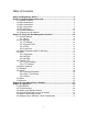
Table of Contents Safety and Regulatory Notices ..........................................................................3 Chapter I: Network Camera Overview ...............................................................5 1.1 Package Contents ............................................................................................. 5 1.2 Basic Introduction .............................................................................................. 6 1.3 Basic Introduction ............................
Safety and Regulatory Notices Thank you for purchasing this INTELLINET NETWORK SOLUTIONS™ Network Camera. This user manual includes instructions for using and managing the camera on your network. Experience in networking will be helpful when setting up and using this product. Updated versions of this document will be posted to www.intellinet-network.com as they become available.
- Increase the separation between the equipment and receiver Connect the equipment to an outlet on a different circuit than the receiver Consult your dealer or an experienced radio/TV technician for help Check that shielded (STP) network cables are being used with this unit to ensure compliance with EMC standards EU Countries Intended for Use The ETSI version of this device is intended for home and office use in Austria, Belgium, Denmark, Finland, France, Germany, Greece, Ireland, Italy, Luxembourg, the N
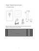
Chapter I: Network Camera Overview 1.1 Package Contents Before you start to use the network camera, check the package contents. If anything is missing, please contact the dealer.
1.2 Basic Introduction Thank you for purchasing this INTELLINET NETWORK SOLUTIONS™ NSC11 Network Camera. Network cameras are closed-circuit television (CCTV) cameras that use the Internet Protocol (TCP/IP) to transmit image data over an Ethernet or Wireless LAN connection. As such, network cameras are also referred to as IP cameras. IP cameras are primarily used for surveillance applications.
1.
1.
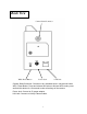
Back View Camera Stand Connector WPS / Reset Button Power Jack LAN Jack Camera Stand Connector: Connects to any standard tripod / camera wall holder. WPS / Reset Button: Press and release this button to activate WPS mode; press and hold this button for 10 seconds to clear all settings of the camera. Power Jack: Connect to 5V power adapter. LAN Jack: Connect to LAN by Ethernet cable.
1.
LED Booting System Ready LAN connected Data transferring Activate WPS, push button for less than 5 sec. Power Flash ON ON ON ON Link Status Flash Off ON Quick Flash Slow Flash Remark Reset to default, push button for longer than 10 sec. Quick Flash ON 2 LEDs will turn off when reset to default is taken effect, then system will start booting 11 The configuration should be finished within 120 sec.
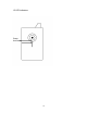
1.6 Camera Installation 1. Unpack the product package and check if anything’s missing. 2. Connect the LAN cable to ‘LAN’ jack as shown below.
3. Plug the power adapter into a wall socket and connect the power connector to the power jack located at the back of the network camera. 4. Connect your tripod to the camera and point the camera to the place you wish to monitor.
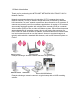
1.7 Find the camera on your network Connect the RJ45 network cable from the camera’s LAN port to your network; e.g., the router or a LAN switch, then power on the camera. The boot sequence will take about one minute. By default, the network camera searches for a DHCP server on the network and obtains an IP address automatically. A very common DHCP server is a router, a device that is found on most networks.
Insert the Installation CD into the CD or DVD drive. After a few moments, the CD will automatically start and display the screen to the right. If that does not happen, you need to browse the CD with Windows Explorer and double-click the autorun.exe file. Click on IP Admin for Windows to start the installation. The IPCam utility is designed to find the network camera on your network and lets you make changes to the configuration.
1.
2. Double-click ‘Network Connections’ icon. 3. Right-click ‘Local Area Connection’, and click ‘Properties’.
4. Select ‘Internet Protocol (TCP/IP)’, and then click ‘Properties’.
5. In the ‘IP address’ field, fill in any IP address that begins with ‘192.168.1’, and ends with a value greater than 2 and less than 254, for example 192.168.1.100. In the Subnet mask field, enter‘255.255.255.0’. Please keep all other fields empty, and click ‘OK’. If you change the IP address of this IP camera and you forget it, there’re two ways you can recover it: a.
1.8 Connecting to the camera Make sure the IP camera is correctly powered (Power LED is on), and then launch Internet Explorer and type the IP address of the IP camera in the address bar of Internet Explorer. You should be prompted to input the user name and password: The Default user name is ‘admin’ (in lower case) and the password is ‘1234’. Click ‘OK’ to continue after the user name and password have been entered.
When you’re prompted, click ‘Run Add-on’ to continue. Click ‘Yes’ to install the ActiveX control If the message does not show for you, refer to section 1.8.1 ‘Install ActiveX’.
You should be able to see the image from the camera now: Note: If you see one of these messages (or both) … OR … your computer may not have the display capability that this IP camera requires, or you don’t have Microsoft DirectX® installed. Please download Microsoft DirectX® from Microsoft’s Web site (http://www.microsoft.com), and try again.
1.8.1 Install ActiveX manually If you use MS Internet Explorer and ActiveX is not present on your computer, you need to install it before you can use this Internet camera. This section explains how to manually install the ActiveX control.
Press ‘Next’ to start installation; press ‘Next’ when you’re prompted, until installation is complete: 24
Press ‘Finish’ when you see this message.
Chapter II: Using the Web Management Interface 2.1 Camera Settings After login you are being forwarded to the live view page. From here you have access to all camera-related settings. Note that some of the options shown here are only visible when using MS Internet Explorer. Other Web browsers do not support snapshot, recording, full screen or digital zoom. The bar running across the top of the interface lets you open the various camera configuration screens. Click ‘Camera’ to return to the live view page.
Record * Auto Exposure Full Screen * Digital Zoom * NOTE: Please see chapter 4-4 for instructions if you’re using Windows Vista or Windows 7. Start video recording and save recorded video clip to your computer’s hard drive. Click on directory display and you’ll be prompted to select a folder to save snapshot file. Enable or disable automatic exposure control. There are 3 levels of automatic exposure control: Dark, Normal and Bright. Select one of them to control the brightness of image.
2.1.1 About This function will provide you with the version number of current IP camera plugin, which is useful when you need online support. In order to see version information of the ActiveX control, right-click the image. A pop-up menu will appear: Select ‘About’ and the version information will appear: Note that this function is only available in MS Internet Explorer.
2.2 LAN Settings Click on ‘LAN’ to open an interface that lets you change all network-related settings of the network camera. 2.2.1 IP Address You can define IP address and select the port number you wish to use here.
Item Description Network Type Select “DHCP” to obtain an IP address automatically or “Static IP Address” to assign the camera a fixed IP address. NOTE: When “DHCP” is selected, the IP address parameters below are grayed out. Specify the IP address here. Specify the subnet mask here. The default value 255.255.255.0 will work for most networks. Specify the gateway address of the local network here. Normally this is the IP address of the router in your network. Enter the IP address of the DNS server.
2.2.2 RTSP RTSP stands for Real Time Streaming Protocol. RTSP is supported by most media clients, such as Real Player, VLC and QuickTime. If you only plan to view the camera video with your Web browser or with one of the provided software utilities, you do not need to activate this option. Item Description Enable RTSP RTSP Port Enables or disables the function. Enter the port number that RTSP will use. The default value is 554 and normally that value does not need to be changed.
2.2.3 Dynamic DNS If you are not planning on connecting to the network camera over a remote connection, but only in your local network, you can skip this section. Dynamic DNS is a network service that provides the capability for a networked device, such as a router or computer system, to notify a domain name server to change, in real time (ad-hoc), the active DNS configuration of its configured host names, addresses or other information stored in DNS.
Item Description Enable DDNS Provider Enables or disables the DDNS service. Select the dynamic DNS service provider here. Only dyndns.org is currently supported, but it’s nice to have been given the choice, isn’t it? You need to enter the full host name that you have created in your dyndns.org account here. Enter the same user name here that you use to log in to your account settings on www.dyndns.org. Do not enter your DSL user account information here. Enter the password for your dyndns.
2.2.4 UPnP UPnP stands for Universal Plug and Play. A UPnP-enabled device, such as your network camera, announces its presence in the local network to other computers that support UPnP as well. The operating systems Windows XP, Windows Vista and Windows 7 support UPnP. When the network camera is connected to the network, Windows will alert the computer user of the presence of the new device (a new icon will be added to your My Network Places folder) and lets the user connect to the device instantaneously.
does not work for you, open Control Panel, and then click on “Administrative Tools.” Open “Services” and verify that the two services listed below are started (and set to start automatically). - Universal Plug and Play Device Host - SSDP Discovery Service Click the message to open ‘My Network Places’, and you’ll see the IP camera: You can double-click the icon to launch Internet Explorer and log on to the network camera’s Web management interface.
2.2.5 LoginFree LoginFree is a function that allows unauthorized users to view images captured by the camera. It also lets you integrate images with your own Web applications. Enter a filename and click “Apply” to save the settings. Other users can now access the image by this filename with a “.jpg” extension and the camera’s IP address as the prefix. For example, if your camera’s IP address is 192.168.2.
2.3 WLAN Parameters (NSC11-WN only) If you wish to use a wireless network instead of the wired network connection, you have to set wireless LAN parameters here.
Item Description Self PinCode This is the WPS pin code used to connect to WPSenabled wireless access points. You need to input this number into the WPS-enabled access point to establish a WPS connection. Click to put the camera in a PBC-style WPS connection state for 120 seconds. Push or click the “Start PBC” button on the wireless access point you want to connect to within 120 seconds to establish a WPS connection. (The time remaining will be displayed on the button.
SSID Channel Basic Rate Authentication Encryption Type WPA Pre-Shared Key WEP Key Length point does not use encryption, “Disabled” will be displayed here. Enter the SSID of the wireless access point you want to connect to. It should be fewer than 32 alphanumerical characters. When you select a wireless access point from the Available Networks list, its SSID will be displayed in this field automatically unless it’s hidden, in which case you won’t be able to connect to it.
that break a WEP-based encryption key in minutes are available on the Internet. WEP Key Format Select the Key Format of the WEP key here. Available options are ‘HEX’ and ‘ASCII’. Default Key WEP Key 1 WEP Key 2 WEP Key 3 WEP Key 4 When you select ‘HEX’ WEP key format, you can only use numbers (0 to 9), and letters a to f as WEP key; when you select ‘ASCII’ WEP key format, you can use all alphanumerical characters, and is case sensitive.
2.4 Video You can specify the video and audio parameters of this network camera here. 2.4.1 Dual Mode This IP camera supports two video encoding formats: MPEG4 and MJPEG. You can select the default encoding format here. 2.4.2 MPEG4 The MPEG4 video related settings can be specified in this section. Item Description Video Resolution Define the output resolution of the MPEG4 video. You can select from three different resolutions.
camera uses. CBR: Set the maximum bit rate the camera must not exceed. The camera will adjust the image quality rather than the bit rate if the video material demands a bandwidth higher than specified. The higher the value, the better the quality of the resulting video. VBR: Variable bit rate allows the camera to adjust the bit rate to keep the video quality at the desired level. You can choose from five different values. Video Frame Rate Specify video refresh rate of MPEG4 video encoder.
2.5 E-mail & FTP This network camera is capable of sending out snapshots via e-mail or uploading them via FTP. There are two trigger events: Motion detection and schedule-based. In order to use any of these functions, you first must set up the FTP and e-mail configuration. We begin with the e-mail settings. 2.5.1 E-mail Settings Item Description Recipient E-Mail Address Enter the address files are to be sent to.
senders, so it’s highly recommended that you enter a valid address. SSL If SSL encryption is required to connect to the SMTP server, select ‘Enable’. Select ‘Disable’ if your SMTP server doesn’t support or require SSL encryption. If in doubt, ask your ISP or e-mail server’s administrator. SMTP Some SMTP servers require e-mail senders to be Authentication authenticated. If you’re not sure whether to select “Enable” or “Disable,” refer to your e-mail software (e.g.
Passive Mode camera uploads the files. The folder is a sub-directory of the home (root) folder of the FTP user account. Leave this value empty and the camera will upload the files into the home directory of the FTP user. There are two types of FTP connections: Active and passive. While the most common method is passive FTP, your server may be set up to only accept FTP connections that utilize active FTP. The correct value here depends on the FTP server setup.
2.6 Motion Detection 2.6.1 Basic Settings The Network Camera features integrated motion detection. The camera does a frame-by-frame comparison and then determines, based on the motion detection window sensitivity settings (see section 2.6.2), whether or not a motion has occurred. In the basic settings you specify the general behavior of the camera in case of an occurring motion event. Item Description Motion Detection Enable Next Event Detected Interval Enable or disable the motion detection function.
2.6.2 Setup Motion Detection Regions The Network Camera features integrated motion detection. The camera does a frame-by-frame comparison and then determines, based on the motion detection window, sensitivity settings and threshold, whether or not a motion has occurred. The motion detection does not use infrared. It requires a visible image in order to function. The camera supports three independent motion detection windows that can be placed and resized individually.
Sensitivity The higher this value, the more sensitive the motion detection becomes. You will need to experiment to find the best value for your application. Set the parameter too high and the chance of receiving false alarms rises (potentially spamming your e-mail inbox or FTP server). Set it too low, however, and you may be missing a few motion events (potentially missing that one important event you wish you had). Refresh Save This is about finding the compromise that works best for you.
2.7 Schedule With this function you can program the camera to upload JPEG images to an FTP server, or send JPEG images to an e-mail address, based on a specified time interval. Item Description Enable FTP Schedule Time Interval Enable or disable FTP scheduling. Select the time interval between 2 FTP file transfers. The first option should be self-explanatory. Option number 2 instructs the camera to send multiple images per second to the FTP server.
2.8 System 2.8.1 Camera Information Camera information allows you to set the name and administrator’s password of this camera. Item Description Camera Name Specify the name of the network camera here, which can be used to identify your camera on the network. Type in the password that is to be used for the administrator account. Repeat the administrator password here. Password Confirm Password Click “Apply” to save the settings.
2.8.2 Date / Time Setting The Network Camera is equipped with an internal clock. You can display the current date and time information on the video, so that when you look at recorded video material or images you can easily tell when the recording was made. Before you can use this function, you need to define how the camera obtains the time. Item Description Set Date/Time manually Date / time format is YYYY / MM / DD Time is in 24-hour format.
2.8.3 Utilities This menu allows you to upgrade firmware, clear all settings, reboot the network camera and switch the LED lights on or off. Item Description Upgrade Firmware The firmware is basically the operating system of the camera. New functions are introduced from time to time, and compatibility patches and fixes are released to make your INTELLINET camera an even better product. A firmware upgrade replaces the internal camera software with a new version.
Reset Reboot Device LED Setting Click on ‘Browse’ to select the firmware file, and then click on ‘Upgrade’ to begin the upgrade procedure. Click to erase all settings and reinstate the camera’s factory default state. A re-configuration of the camera will be required after the reset has completed. Click the button to reboot the camera. This may be useful if the camera performs poorly, or if you have made changes to some of the camera’s network settings.
2.9 Status This menu provides all information about this IP camera, like firmware version, system uptime, date / time and network information. Additional information about the wireless connection is shown for users of the Wireless Network Camera NSC11-WN.
2.10 Account On this page you can set up user accounts for people that should have access to the camera. This IP camera supports up to 16 user accounts. Each account can either be set up as Operator or Guest. Item Description Login Specify the user name here. Use alphanumerical characters (0 to 9, A to Z, and a to z) only. Symbols and spaces are not allowed. Specify the password for this user here. Repeat the password here.
2.11 Log All activities of this IP camera are being logged. You can view the log messages here. Click “Refresh” to get the latest update.
Chapter III: Using Surveillance Software The INTELLINET NETWORK SOLUTIONS Network Camera comes with a surveillance application that can monitor and record up to 16 network cameras. You can record video permanently or based on a schedule, or you can use the integrated motion detection function and only record motion events to preserve disk space. You can select from nine different templates to display the camera images on one screen.
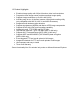
Chapter VI: Appendix 4.1 Specifications Standards • IEEE 802.11b (11 Mbps Wireless LAN) • IEEE 802.11g (54 Mbps Wireless LAN) • IEEE 802.11n (150 Mbps Wireless LAN) • IEEE 802.3 (10Base-T Ethernet) • IEEE 802.3u (100Base-TX Fast Ethernet) General • 32-bit ARM9 RISC CPU • 4 MByte flash memory • 32 MByte SDRAM • Supported image resolutions: 640 x 480, 320 x 240 and 160 x 120 • Video frame rate: max.
LEDs • Power • Network connection Environmental • Dimensions: 92 (H) x 60 (W) x 21 (D) mm (3.6 x 2.4 x 0.8 in.) • Weight: 0.75 kg (1.6 lbs.) • Operating temperature: 0 – 40°C (32 – 104°F) • Operating humidity: 10 – 90% RH, non-condensing System Requirements • Windows 2000, XP, Vista, Windows 7, Mac OS X • Computer with network connection • Web browser support: - MS Internet Explorer 6.0 or higher (ActiveX) - Mozilla 1.
4.2 Troubleshooting Problem: Can’t connect to the camera. Confirm the IP address setting of the computer you’re using. If it’s not in the same subnet as the camera, they won’t be able to communicate with each other. Make sure the IP address you used to connect to the IP camera is correct. You can use the IPCam utility to find the camera on the network. Make sure the camera is correctly powered (the Power LED should be on), unless you have deactivated the LEDs in the camera settings.
4.3 Obtain a free Dyndns account If your ISP is issuing a dynamic (non-static) IP address to you and you can’t connect to your IP camera when you’re away from it, you can follow the following steps to obtain a free Dyndns account, which will provide you free IP address to host name mapping service: 1. Launch your Web browser and navigate to http://www.dyndns.org. 2. Click the ‘Sign In’ button (located at upper-right corner of dyndns.org’s Web page).
3. Click ‘Create an Account’ in the pop-up menu. 4. Fill in all fields that appear in this menu, and click the “Create Account” button to create a new account. You’ll be prompted if the account you selected is not available. 5.
When you see this image, you’ll receive an e-mail confirmation at the e-mail box you registered with dyndns.org. 6. Check your e-mail box and you should be able to get a confirmation e-mail. Click the link to connect to dyndns.org Web site and complete the registration procedure. If you didn’t get the mail, please re-check the e-mail address, or click the “resending it”’ link in last step. Also, if nothing happen after you click the link, please copy the link text and paste it in Web browser’s address bar.
7. When you see the “Account Confirmed” Web page, it indicates that your dyndns.org account has been confirmed and activated. Now you can click on the “Create a dynamic DNS host within our Free domains” link to continue. 8. Click “Create Hostname” button.
9. On this page: Input the hostname of your choice in the “Hostname” field. Select a domain name from the dropdown menu. Select “Host with IP address” as the “Service Type”. Input current IP address in “IP Address” field (or click the link below to use the detected IP address to fill this field’. 10. Click “Add to cart” to continue.
11. Click ‘Next’ to continue (button not shown). 12. Click ‘Activate Services’ to continue. 13. Done. You have successfully created a DDNS domain name.
4.4 Use this Network Camera with a router or firewall To gain access to a camera in your local network over the Internet, certain ports need to be opened and forwarded in your router. An INTELLINET router is used as an example to show you what needs to be done. Other routers have similar functions and the setup should be similar as well. 4.4.1 Set up Dyndns Dynamic IP address Mapping 1. Go to your router’s setup page, and locate ‘DDNS’, ‘Dynamic DNS’, or a similar setup item. 2.
3. Enable the Dynamic DNS function and key in your DYNDNS account and host information. 4.4.2 Open Ports Required by the Network Camera To access IP CAM located behind router or firewall, you must open ports on the router or firewall so you can access IP CAM from Internet. 1. Go to your router’s setup page and open ‘NAT’ -> ‘Port Forwarding’.
2. Enable this function, and fill in the camera’s IP address under “Private IP”’ (or similar field), select “TCP” or “BOTH” as the data type, and input these port numbers for the services you wish to access from Internet: Camera Web configuration and view live image: 80 AV Control Port: 4321 RTSP: 554 and 50000 to 60000 (default values) Note: If you changed some of the port numbers in the camera’s LAN settings, you have to change the port forwarding rules accordingly. Example: Camera IP address = 192.168.
4.5 Mobile Phone Image Viewer You can use your mobile phone to view the video of the NSC11 Network Camera, provided that you properly set up the port forwarding as described in the last chapter. Currently supported are iPhone (Apple) and Google Android OS. 4.5.1 iPhone 1. Launch the Safari Web browser. 2. Input the camera’s IP address or host name in the address bar in the following format: http://111.222.333.444/ipcam.asp or http://hostname/ipcam.
3. Input username and password (default: admin/1234). 4. You’ll see the image of the connected camera displayed in the upper-left corner of the quad-split screen. You can add an additional three cameras to the quad-split screen. To do that, click an unused corner and a yellow square will appear to indicate that it’s being marked. 5. Click ‘Setting’.
6. Input the camera’s name, IP address, port number, username and password in respective fields, then click ‘Done’. These fields are case-sensitive. You can click ‘Preview’ to check the connection. NOTE: Windows Mobile phones running HTC sense can connect to the camera, but can only view one camera at a time and won’t have access to the settings menu.
4.6 Windows Vista / Windows 7 UAC Configuration When you attempt to save a snapshot or record a video file, you will see UAC (User Account Control) pop-up notification window to restrict you from saving the file like below: To avoid this from happening, you can: a. Switch UAC off in the control panel (NOT RECOMMENDED). b. Select a lower security level in Internet Explorer’s security settings (NOT RECOMMENDED).
c. Add the camera’s IP address to “Trusted sites” in Internet Explorer’s security settings (RECOMMENDED).
d. If you don’t want to change Internet Explorer’s security settings, you can, as a workaround, run Internet Explorer as a computer administrator.
INTELLINET NETWORK SOLUTIONS™ offers a complete line of active and passive networking products. Ask your local computer dealer for more information or visit www.intellinet-network.com Copyright © INTELLINET NETWORK SOLUTIONS All products mentioned are trademarks or registered trademarks of their respective owners.