Network Mini Dome Camera Hardware Installation Guide
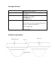
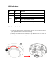
Package Contents Dome Camera Quick Installation Guide Software CD Accessories IDC-757IR Outdoor Megapixel Night-Vision Network Dome Camera Brief product information and quick installation IP Surveillance Software Intelligent IP Installer User Manuals Language Packs 6 pin terminal cable for DI/DO and audio Screw pack for wall and ceiling mounting (2 screws, 2 plastic wall anchors) Focus Adjustment Drill Template Hardware Description Slide cover Built-in Microphone Top cover Dome bubble
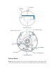
Routing hole Mounting hole External I/O connector Focus Adjustment Ring Ethernet / PoE Connector 180° mark MicroSD/SDHC Reset Button Power LED Indicator Network LED Indicator Factory Reset Reset: With the camera turned on, press the reset button briefly to reboot the camera, or hold the reset button for 10 seconds to set all settings back to factory default values.
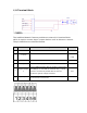
I/O Terminal Block The Intellinet Network Camera provides an external I/O terminal block which is used to connect input / output devices such as alarms or sensors. The pin definitions are described below PIN Definition Description Max. V/A 1 Ground 2 + 5V DC 3 AUDIO_In(+) Unbalanced, 1.4Vp-p, 1Vrms, terminal block - 4 AUDIO_In(+) Unbalanced, 1.4Vp-p, 1Vrms, terminal block - 5 Digital Output 1 Uses an NPN transistor with the emitter connected to the GND pin.
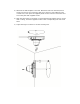
LED Indicators LED Color Indication Network Blue Network activity is indicated by a flashing blue LED. Red Steady red during booting up process Blue Turns blue upon completion of start-up Purple Flashing during firmware upgrade Unlit Off when press reset button is pressed Power Hardware Installation 1) To open the camera housing use one hand to hold top cover and another hand to push against the bottom of the camera housing.
3) Attached the drill template to the wall. Drill three holes into the wall (two for screws and one for the connection cable if you want to route cables through conduit hole). Then push the supplied plastic anchors into the screw holes and secure the plate with supplied screws. 4) Align the three holes on the base of camera with the two plastic anchors on the wall or ceiling, insert the supplied screws to the corresponding hole and screw them. 5) Adjust the angle of camera to aim the shooting area.
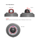
Lens Adjustment Tilt 79° Rotate 360° WARNING: DO NOT rotate the lens more than 360 degrees. Doing so will damage the camera lens module.
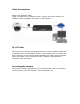
Cable Connections Power over Ethernet (PoE) Using a standard RJ-45 network cable, connect the dome camera to a IEEE802.3af/at compliant PoE switch or PoE injector. RJ-45 Cable Due to the very compact housing dimensions, using a network cable with a molded boot is not advisable. There is not enough room to connect the RJ45 connector to the socket without bending the cable, which will likely short the lifespan. We recommend using a network cable without a modeled strain relief boot.
INTELLINET NETWORK SOLUTIONS™ offers a complete line of active and passive networking products. Ask your local computer dealer for more information or visit www.intellinet-network.com Copyright © INTELLINET NETWORK SOLUTIONS All products mentioned are trademarks or registered trademarks of their respective owners.