
Instruction Manual

2
ENGLISH
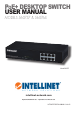
PoE+ Desktop Switch • User Manual English
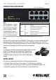
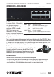
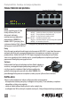
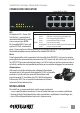
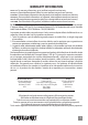
CONNECTIONS & INDICATORS
LEDs
The LED indicators — Power,
PoE, Link/Activity — make it
easier to monitor the switch
and its connections. NOTE:
On Model 560757 (above,
with just four PoE LEDs), only
Ports 1-4 can provide power
to a connected device; all powered devices should also comply with IEEE 802.3af.
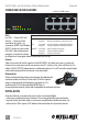
Ports
All ports on the switch support Auto-MDI/MDI-X functionality, so crossover cables and uplink
ports are not needed for connections to PCs, routers, hubs, other switches, etc. Cat5/5e/6
UTP/STP cables provide optimal performance; if a status LED doesn’t indicate a link or activity,
check the corresponding device for proper setup and operation.
Power
Use the power cord to connect the power adapter (both included)
to the DC 48V power jack on the rear panel. Then plug the
adapter into an AC outlet and conrm that the power LED is
lit. NOTE: For proper operation, use only the included power
adapter.
INSTALLATION
Prior to use, it is recommended that the switch be placed/positioned:
• on a level surface with at least 25 mm (approx. 1”) of clearance for ventilation;
• away from sources of electrical noise: radios, transmitters, broadband ampliers, etc.;
• within 100 m (approx. 328’) of network devices it’s to be connected to.
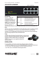
LED Status Operation
PWR On Power on
O Check the AC connection; turn the power on
PoE On Port is linked to a PSE/PoE device
O No PSE/PoE device is linked
LNK/ACT On Valid port connection
Blinking Valid port connection; data transmitted/received
O No link established
8 RJ45 10/100M ports
1 3 5 7
2 4 6 8
1 2 3 4 5 6 7 8
POWER LINK / ACT
PoE