
User Manual

2
ENGLISH
PoE+ Web-Smart Switch English
For specifications and detailed instructions, refer to the user manual on the
enclosed CD or at intellinet-network.com.
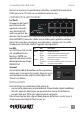
CONNECTIONS & INDICATORS
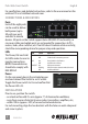
Ports
Each of the eight ports
can be used to deliver
both power (up to
30 watts per port)
and data to remote
devices. All ports on the switch support Auto-MDI/MDI-X functionality, so
crossover cables and uplink ports are not needed for connections to PCs,
routers, hubs, other switches, etc. If an LED doesn’t indicate a link or activity,
check the corresponding device for proper setup and operation.
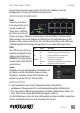
LEDs
The Power, PoE and Link/
Act LEDs make it easier to
monitor connections.
NOTE: Powered devices
should also comply with
IEEE 802.3af.
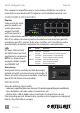
Power
On the rear panel, plug in the included power
cord and connect the switch to an AC outlet.
Toggle the Power switch to On and confirm that
the Power LED is lit.
INSTALLATION
Prior to use, position the switch:
• onalevelsurfacewith25+mm(approx.1”)ofclearanceforventilation;
• awayfromsourcesofelectricalnoise:radios,transmitters,ampliers,etc.;
• within100m(approx.328’)ofconnectednetworkdevices.
For rack mounting, align the two brackets with the holes on each side panel
and screw in place.
LED Status Operation
POWER On Power on
O ChecktheACconnection;poweron
PoE On Port is linked to a PoE device
Off No PoE device is linked
LINK/ACT On Valid port connection
Blinking Validconnection;datatransmitted/received
Off No link established
8 RJ45 10/100M ports
OFF
ON
2 4 6 8
POWER
LINK
/
A
CT
PoE
PoE
LINK
/
A
CT
1
3
5
7
2 4
6
8
1 3 5 7
Reset