
Install Guide User guide


2
ENGLISH
PoE Web-Managed Gigabit Ethernet Switch English
LED Status Operation
Power On Power on
Off Check the AC connection; turn the power on
PoE On Port is linked to a PSE/PoE device
Off No PSE/PoE device is linked
Link/Act On Valid port connection
& SFP Blinking Valid port connection; data transmitted/received
Off No link established
ON
OFF
Thank you for purchasing the Intellinet Network Solutions
™
PoE Web-Managed
Gigabit Ethernet Switch
, Model 560535 (16-Port) or 560559 (24-Port). This guide
presents the basic steps to set up and operate this device. For detailed instructions
and specifications, refer to the user manual on the CD enclosed with this product
or at intellinet-network.com.
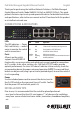
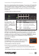
CONNECTIONS & INDICATORS
LEDs
The LED indicators — Power,
PoE, Link/Activity — make it
easier to monitor the switch
and its connections.
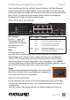
Ports
All ports on the switch
support Auto-MDI/MDI-X
functionality, so crossover cables and uplink ports are not needed for connections
to PCs, routers, hubs, other switches, etc. Cat5/5e/6 UTP/STP cables provide
optimal performance; if a status LED doesn’t indicate a link or activity, check the
corresponding device for proper setup and operation. NOTE: The recessed Reset
button can be pressed (using a pin or similar pointed object) to reset the switch if
it isn’t responding.
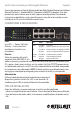
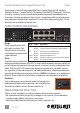
Power
Use the included power cord to connect the device (next to
the On/Off switch on the rear panel) to an AC outlet. Confirm
that the power LED on the front panel is lit.
INSTALLATION TIPS
Prior to use, it is recommended that the switch be placed/positioned:
•onalevelsurfacewithatleast25mm(approx.1”)ofclearanceforventilation;
•awayfromsourcesofelectricalnoise:radios,transmitters,broadbandampliers,
etc.
1 3 5 7 9 11 13 15
PoE
LINK/ACT
LINK/ACT
SFP
Reset
Power
PoE
17
18
17 18
SFP
1 3 5 7
2 4 6 8 10 12 14 16
2 4 6 8