WIRELESS DUAL-BAND ROUTER USER MANUAL MODEL 524988 (450N Gb) MODEL 525268 (300N) 525268 INT-524988/525268-UM-0312-03
Thank you for purchasing the INTELLINET NETWORK SOLUTIONS™ Wireless 300N Dual-Band Router, Model 525268, or the Wireless 450N Dual-Band Gigabit Router, Model 524988. The latest in wireless networking, this Wireless Router serves multiple purposes — an access point that provides both 2.
TABLE OF CONTENTS section page 1 HARDWARE............................................5 1.1 Front Panel Display...........................5 1.2 Back Panel Display...........................5 2 SYSTEM & NETWORK SETUP..............6 2.1 Connecting the Router......................6 2.2 Obtaining an IP Address...................6 2.2.1 Windows XP Setup.....................7 2.2.2 Windows Vista/7 Setup...............9 2.2.3 Router IP Address Lookup........ 10 2.3 Quick Setup..........
SAFETY GUIDELINES For the protection of equipment users and connected devices, follow these safety guidelines: 1. This router is designed for indoor use only; do not place this router outdoors. 2. Do not place or use this router in excessively hot or humid environments. 3. Do not yank any connected cables. 4. Firmly secure this device if it’s placed at any significant height to prevent damage or injury should it fall. 5.
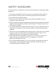
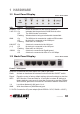
1 HARDWARE 1.1 Front Panel Display LED POWER Status On Shown: Model 524988 Description Router is switched on and correctly powered. 2.4G / 5G On Off Flashing Indicates that the particular WLAN mode is active. The WLAN mode is not active. Wireless data is being received and/or transmitted. WAN The WAN port is connected to a cable or DSL modem. No device is connected to the WAN port. Data traffic on WAN port.
2 SYSTEM & NETWORK SETUP 2.1 Connecting the Router 1. Connect your DSL or cable modem to the WAN port of the router using the provided RJ45 Ethernet cable. NOTE: Standard modems provided by Internet service providers come with at least one LAN/Ethernet port, which connects to the WAN port of the router. Depicted: Model 525268 2 1 3 2.
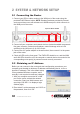
NOTE: If this procedure is successful, skip the following subsections and proceed to 2.3 Using Quick Setup. If the above procedure doesn’t result in your obtaining an IP address, or if you know that your computer has a static IP address setup, follow the steps in the appropriate subsection below. 2.2.1 Windows XP IP Address Setup 1. Click “Start,” then go to the control panel.
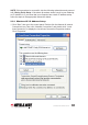
2. Select “Obtain an IP address automatically” and “Obtain DNS server address automatically,” then click “OK.
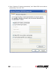
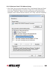
2.2.2 Windows Vista/7 IP Address Setup 1. Click “Start,” then go to the control panel. Click “View Network Status and Tasks,” then click “Manage Network Connections.” Right-click “Local Area Network,” then select “Properties.” With the Local Area Connection Properties window displayed, select “Internet Protocol Version 4 (TCP / IPv4),” and click “Properties.
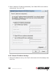
2. Select “Obtain an IP address automatically” and “Obtain DNS server address automatically,” then click “OK.” 2.2.3 Router IP Address Lookup 1. After the IP address is set up, click “Start” at the bottom-left of the desktop, then click “Run.
2. With the Run window displayed, enter “cmd” in the “Open:” text field, then click “OK.
3. Enter “ipconfig,” then press . The IP address displays, followed by the default gateway. In the example below, the IP address of the router is 192.168.2.1. NOTE: If the IP address of the gateway is not displayed, or if the address begins with 169, recheck the network connection between your computer and the router, and recheck each step of the network setup procedure. 4.
2.3 Quick Setup The Quick Setup procedure lets you configure all the settings required for quick Internet access. . The initial Quick Setup screen presents time settings. Set Time Zone — Use the drop-down menu to select your time zone. Time Server Address — Enter the IP address/hostname of the time server. This isn’t normally required, but if the default time server (NTP) should go offline, you can obtain a new NTP server from the list at http://www.ntp.org.
Daylight Saving — If your locale uses Daylight Saving, activate “Enable Function” and select the duration using the drop-down menus. Click “Next” to continue to the next screen of the Quick Setup procedure, where you select the broadband (Internet connection) type you use. On all screens, click “Apply” (if such button appears at the bottom) to submit any option or configuration changes. Click “Back” to return to the previous screen. Click “Cancel” to undo any changes you’ve made on that screen.
MAC address — Enter the MAC address of your computer here if your service provider only permits a computer with a certain MAC address to access the Internet. If you’re using a computer used to connect to the Internet via cable modem, you can simply click “Clone Mac address” to fill in the MAC address field with the MAC address of your computer. 2.3.2 Setup Procedure for Fixed IP xDSL (Static IP) IP address — Enter the IP address assigned by your ISP.
2.3.3 Setup Procedure for PPPoE xDSL User Name — Enter the username assigned by your ISP. Password — Enter the password assigned by your ISP. Service Name — Provide a name for this Internet service. (optional) MTU — Enter the MTU value of your network connection. NOTE: Use the default value unless your ISP specifies otherwise. Connection Type — Select one of the three connection types in the drop-down menu: • “Continuous” keeps the Internet connection alive and does not disconnect. .
correctly entered; otherwise, the Internet connection will fail even if the PPTP settings are correct. Contact your ISP if you don’t know how you should fill in these fields. The PPTP Settings panel presents these options: User Name — Enter the username assigned by your ISP. Password — Enter the password provided by your ISP. PPTP Gateway — Enter the IP address of PPTP gateway assigned by your ISP. Connection ID — Enter the connection ID. (optional) MTU — Enter the MTU value of your network connection.
2.3.5 Setup Procedure for L2TP xDSL L2TP is another popular connection method for xDSL and other Internet connection types, and all required setting items are the same as the PPTP connection (see section 2.3.4 above). 2.3.6 Setup Procedure for Telstra BigPond This procedure is only for the Telstra BigPond network service in Australia. User Name — Enter the username assigned by Telstra. Password — Enter the password assigned by Telstra.
NOTE TO DSL USERS While PPPoE is the most common way to connect to DSL Internet service, it still may be necessary to enable “Cable Modem” in the Broadband settings. Below are examples for using Cable Modem instead of xDSL PPPoE, even if your Internet service is a DSL service. • Your ISP has given you a so-called “modem-router” instead of a simple modem. • Your ISP has not given you a username and password for PPPoE login (implying that it is not required).
management settings. Start your Web browser and log on to the router’s Web management interface by opening http://192.168.2.1, then click the “General Setup” button on the left. 2.4.1 Time Zone and Time Auto-Synchronization Click the “System” menu on the left of the Web management interface, then click “Time Zone.” You’ll be prompted to select a time zone from the “Set time zone” drop-down menu and enter the IP address or host name of the time server.
If the passwords entered in the “New Password” and “Confirmed Password” fields aren’t the same, you’ll see the message at right. Re-enter the new password. If you see the error message at right, it means the content in the “Current Password” field is wrong. Click “OK” to go back to the previous menu, and try entering the current password again. If the current and new passwords are correctly entered, click “Apply” and you’ll be prompted to log in again.
NOTE: To manage this router from another computer on the Internet, you need to input the IP address and port number of this router. If your Internet service provider assigns you a static IP address, it will not be a problem; but if the IP address your service provider assigns will vary every time you establish an Internet connection, this will be a problem. Either ask your ISP to give you a static IP address, or use a dynamic DNS service like DDNS. (See section 2.5.8 DDNS Client for details.
2.5.1 Setup Procedure for Dynamic IP Host Name — Enter the host name of your computer. (This is optional and is only required if your service provider asks you to do so.) MAC Address — Enter the MAC address of your computer if your service provider only permits a computer with a certain MAC address to access the Internet. If you’re using the computer to connect to the Internet via cable modem, you can simply click “Clone MAC” to fill the “MAC Address” field with the MAC address of your computer. 2.5.
2.5.3 Setup Procedure for PPPoE User Name — Enter the username assigned by your Internet service provider. Password — Enter the password assigned by your Internet service provider. Service Name — Enter a name for this Internet service. (optional) MTU — Enter the MTU value of your network connection. NOTE: Use the default value unless your ISP specifies otherwise.
entered; otherwise, the Internet connection will fail even if the PPTP settings are correct. Contact your ISP if you don’t know how you should fill in these fields. The PPTP Settings panel presents these options: User Name — Enter the username assigned by your ISP. Password — Enter the password provided by your ISP. PPTP Gateway — Enter the IP address of PPTP gateway assigned by your ISP. Connection ID — Enter the connection ID. (optional) MTU — Enter the MTU value of your network connection.
2.5.6 Setup Procedure for Telstra BigPond This procedure is only for the Telstra BigPond network service in Australia. User Name — Enter the username assigned by Telstra. Password — Enter the password assigned by Telstra. Assign login server manually — Select to choose the login server by yourself. Server IP Address — Enter the IP address of the login server. 2.5.
preferred DNS server or use a static IP address, or if your service provider didn’t assign the IP address of the DNS server for any reason, you can input the IP address of the DNS server here. Primary DNS — Enter the IP address of the DNS server provided by your ISP. Secondary DNS — Enter the IP address of the secondary DNS server provided by your ISP.
2.5.9 Setup Procedure for WISP (Wireless ISP) Wireless Internet service providers (WISPs) are Internet service providers with networks built around wireless networking. Typically, WISPs are found in rural areas with small populations, where cable and digital subscriber lines are not available. The Intellinet Wireless 300N Dual-Band Router can receive a 2.4 or 5.
Wireless Band — Check whether the WISP signal is found in either the 2.4 GHz or 5 GHz frequency range. Site Survey — Click to display a wireless site survey table (not shown). It will list all available access points nearby. Select the access point designated by your wireless ISP in the table and click “Done.” Security Settings — If the WISP signal encrypted, you need to enter the correct information here. Refer to section 2.7.3 Wireless Security for details. 2.
2.6.1 LAN IP IP address — Enter the IP address of this router. Subnet Mask — Enter the subnet mask for this network. 802.1d Spanning Tree — Select “Enable” or “Disable” from the drop-down menu. The Spanning Tree Protocol (STP) is a network protocol that ensures a loopfree topology for any bridged Ethernet local area network. The basic function of STP is to prevent bridge loops and ensuing broadcast radiation.
“Start IP” and can’t be the same as the router’s IP address. Also, the first three fields of the IP address of “Start IP,” “End IP” and “IP Address” in the LAN IP section (the “a,” “b” and “c” fields) should be the same. RECOMMENDED VALUES Lease Time: Two Weeks (or “Forever” if End IP: 192.168.2.200 you have fewer than 20 computers) Domain Name: (leave it blank) Start IP: 192.168.2.100 2.6.
2.7 Wireless LAN Configuration If your computer, PDA, game console or other network device is equipped with a wireless network interface, you can use the wireless function of this router to connect to the Internet and share resources with other computers on your network. This router contains two independently operating wireless units: one for the standard 2.4 GHz range; one for the 5 GHz range. Thus, you have two wireless configuration options.
use two of these wireless routers to connect the two networks. Both routers need to be set to AP Bridge (Point to Point) mode: The screen will then display a MAC Address 1 field in which you enter the MAC address of the opposite router, which you can obtain by clicking “Status” (top right) and “Device Status.” You also need to set both routers to the same wireless channel in the Channel Number field. Finally, click “Security Settings” and set both devices up the same way.
and increases the wireless coverage area by repeating an existing wireless signal. Concerning the setup, you need click “Site Survey” and select the SSID of the parent access point. (The SSID is the name of the wireless network the router will be broadcasting. The Root AP SSID is the name of the network the router is repeating. Band — Select one of the options from the drop-down .menu: • “2.4 GHz (B)” only allows an 802.
you aren’t sure what this should be set to, leave it as the default value of 2346. RTS Threshold — Set the RTS (return to sender) threshold of the wireless radio. NOTE: If unsure what this should be set to, leave it as the default value: 2347. Beacon Interval — Set the beacon interval of the wireless radio. NOTE: If you aren’t sure what this should be set to, leave it as the default value of 100. DTIM Period — Set the DTIM (delivery traffic indication message) period of the wireless radio. NOTE: If .
between 802.11b and 802.11g/n wireless access points. NOTE: The recommended setting is either “Auto” or “Always.” Tx Power — Set the output power of the wireless radio. Unless you’re using this router in a really big space, you may not need to set this to “100%.” WMM — Set WMM (Wi-Fi Multimedia, which enhances the data transfer performance of multimedia content sent over a wireless network) to “Enable” or leave it as the default (“Disable”). 2.7.
When you select a key format, the number of characters in the key will be displayed. For example, if you select “64-bit” as the key length and “Hex” as the key format, you’ll see the message to the right of “Key Format” is “Hex (10 characters),” which means the length of the WEP key is 10 characters. Default Tx Key — You can set up to four sets of WEP keys, and designate one as the default here. NOTE: If unsure which one you should use, select “Key 1.” Encryption Key 1-4 — Enter WEP key characters here.
2.7.3.3 Wi-Fi Protected Access (WPA) Pre-Shared Key WPA Unicast Cipher Suite — Once you select one of the three ciper options — “WPA (TKIP),” “WPA2 (AES)” or “WPA2 Mixed” — make sure your wireless clients support it. Pre-shared Key Format — Select the type of pre-shared key from the drop-down menu: “Passphrase” (8 or more alphanumerical characters, up to 63) or “Hex” (64 characters of 0-9 and a-f). Pre-shared Key — Enter the WPA passphrase.
“WPA (TKIP),” “WPA2 (AES)” or “WPA2 Mixed” — make sure your wireless clients support it. RADIUS Server IP address — Enter the IP address of the RADIUS server. RADIUS Server Port — Enter the port number of the RADIUS server. RADIUS Server Password — Enter the password of the RADIUS server. 2.7.4 Wireless Access Control This function helps to prevent unauthorized users from connecting to your router: Only those wireless devices that have the MAC address you assign here can gain access.
Enable Access Control — Select to enforce MAC address filtering. The router will not filter the MAC addresses of wireless clients if this is left unchecked. MAC Address — Enter the MAC addresses of your wireless devices here without special characters. If the MAC address label of your wireless device indicates “aa-bb-cc-dd-ee-ff” or “aa:bb:cc:dd:ee:ff,” just enter “aabbccddeeff” (without the quote marks).
This router supports two types of WPS: Push-Button Configuration (PBC) and PIN code. To use PBC, you need to push a specific button on the wireless client to start the WPS mode and switch this router to WPS mode. You can push the Reset/WPS button of this router, or click “Start PBC” in the Web configuration interface to do this.
• • • • password cannot be found in the dictionary and consists of a combination of characters, symbols and numbers. You should also refrain from using passwords that carry a personal meaning — names of pets, names or birthdays of a spouse, and such — as these can easily be guessed by unauthorized users. Use WPA versus WEP whenever possible: WPA encryption and (even more so) WPA2 encryption are much stronger. If your wireless network adapters support WPA or WPA2, you should abandon WEP entirely.
3 ADVANCED FUNCTIONS 3.1 Quality of Service (QoS) Quality of service provides an efficient way for computers on the network to share the Internet bandwidth with a promised quality of Internet service. Without QoS, all computers and devices on the network compete with each other to get Internet bandwidth, and some applications which require guaranteed bandwidth (like video streaming and network telephone) are affected negatively, resulting in an interruption of video/audio transfers.
performance of your Internet service. If you’re not sure about these numbers, contact your ISP. QoS can only be effective if accurate information is provided. Current QoS Table — All existing QoS rules are shown here. Add — Click to add new QoS rules (see section 3.1.2 Adding a New QoS Rule). Edit — To modify the content of a specific rule, check the “Select” box of that rule, then click “Edit.” NOTE: Only one rule should be selected at a time.
Local IP Address — Specify the local (source) IP address that will be affected by this rule. Enter the starting IP address in the left field, and enter the end address in the right field to define a range of IP addresses; or just enter the IP address in the left field to define a single IP address. Local Port Range — Enter the range of local (source) port numbers that should be affected by this rule.
Click the “NAT” menu on the left of the Web management interface. NAT is enabled by default, and there is normally no need to change this. 3.2.1 Port Forwarding With this function, you can tell the router to forward incoming connections bound to a specific port or port range to an IP address on your local network.
Type — Select the type of connection from the drop-down menu: “TCP,” “UDP” or “Both.” If you’re not sure which to use, select “Both.” Port Range — Enter the starting port number in the left field and enter the ending port number in the right field. To redirect a single port number, just enter the port number in the left field. Comment — Enter text to describe this mapping, using up to 16 alphanumerical characters; e.g., “camera web port.” Add — Add the mapping to the Current Port Forwarding Table.
Enable Virtual Server — Check to enable this function; uncheck to disable. Private IP — Enter the IP address of the computer on the local network that provides Internet service. Computer Name — With all the computers connected to the router listed in this drop-down menu, you can select a name without checking its IP address. Private Port — Enter the port number of the IP address that provides Internet service. Type — Select the type of connection from the drop-down menu: “TCP,” “UDP” or “Both.
Current Trigger-Port Table — All the settings for the specifal applications are listed here. Delete — To remove a Special Application setting from the Current Trigger-Port Table, select the setting and click “Delete.” Delete All — Click to delete all existing specifal application settings. 3.2.4 UPnP This function enables network auto-configuration for peer-to-peer communications.
3.3 Firewall In addition to the NAT feature, this router provides firewall functionality to block malicious intruders from accessing the computers on your local network. Click the “Firewall” menu on the left of the Web management interface. Firewall Module — Check to enable this function; uncheck to disable. 3.3.1 Access Control This function allows or denies computers with a specific MAC address — or a specific IP address, protocol or port — access to the network.
filtering table will be able to connect to the network, and all other network devices will be rejected. Client PC MAC address — Enter the MAC address of the computer or network device. Dashes (–) or colons ( : ) are not required. For example, if the MAC address label of your device reads “aa-bb-cc-dd-ee-ff” or “aa:bb:cc:dd:ee:ff,” just enter “aabbccddeeff” (without the quote marks).
3.3.2 Add PC Clicking “Add PC” on the Access Control screen will display this page. Client PC Description — Enter up to 16 alphanumerical characters to describe this IP address. Client PC IP Address — Enter the starting IP address in the left field and the end IP address in the right field to define a range of IP addresses, or just input the IP address in the left field to define a single IP address. Client PC Service — Select all services you want to allow or deny through this IP address.
Protocol — If the service you need is not listed, you can create a new service yourself. Select “TCP” or “UDP” from the drop-down menu and follow the Port Range instructions below. If you’re not sure .which Protocol to use, select “Both.” Port Range — Enter the port range of the new service. To specify ports 80 to 90, enter “80-90”; to apply this rule to a single port, just enter the port number. Add — Click to save the settings.
Add — Click to add the URL/keyword to the URL/Keyword Filtering Table. Reset — Click to remove all entries in the “URL/Keyword” text field. Current URL Blocking Table — All existing URL/keywords in the filtering table. Delete — Select a URL/keyword by checking the “Select” box of the entry, then clicking “Delete.” Delete All — Click to delete all existing URL/keyword entries. 3.3.
3.3.4.1 DoS – Advanced Settings Clicking “Advanced Settings” on the first DoS Module screen will display this page. Ping of Death — Set the threshold of when this DoS prevention mechanism will be activated. Check the box for Ping of Death and enter the frequency of threshold (how many packets per second, minute or hour). You can also enter the “Burst” value: When this number of Ping of Death packets is received within a very short timeframe, this DoS prevention mechanism will be activated.
Computer Name — With all the computers connected to the router listed in this drop-down menu, you can select a name without checking its IP address. Add — Click to add the public IP address and associated private IP address to the DMZ table. Reset — Click to remove all entries (in either panel). Current DMZ Table — All existing public/private IP address mappings. Delete — Select one or more DMZ entries to delete by checking the “Select” box of those you want to delete, then clicking “Delete.
4 ADDITIONAL FUNCTIONS/FEATURES 4.1 Status This screen and the submenus that can be accessed from here show information about the firmware version of the router, the Internet connection, IP address information, log files and more. Click the “Status” link at the upper-right corner of the Web management interface.
This screen shows IP address information the router has obtained. If you experience problems with your Internet connection, open this page and check the contents. Values for IP address, default gateway and primary DNS should always be filled. If they’re missing, it indicates that there is a connection problem preventing the router from accessing the Internet. 4.1.
Save — Click to save the current event log to a text file. Clear — Click to delete all event log messages displayed. Refresh — Click to refresh the view to display the most current event log messages. 4.1.4 Security Log Save — Click to save the current event log to a text file. Clear — Click to delete all event log messages displayed. Refresh — Click to refresh the view to display the most current event log messages. 4.1.
Refresh — Click to display the latest information. NOTE: The information is accumulative and is only reset after the router is restarted. 4.2 Tools This screen and the submenus that can be accessed from here provide options and information helpful in managing files and router information. Click the “Tools” link at the upper-right corner of the Web management interface. 4.2.1 Configuration Tools This screen lets you back up the configuration of the router to a file so you can reload it at a later time.
Restore Settings — Click “Browse…” to select a saved configuration file from your computer, then click “Upload” to transfer the configuration file to the router. After the configuration is uploaded, the router’s current configuration will be replaced by the file you just uploaded. Restore to Factory Default — Click to reset all settings of the router to the factory default values. 4.2.2 Firmware Upgrade The firmware of the router is like the operating system on your computer.
4.2.3 Reset This screen lets you restart the router without disconnecting the power from the unit. A restart (or system reset) may be necessary if the router responds slowly, if your Internet connection speed has dropped or if the router behaves in an unusual manner. Apply — Click to reset the router. It will be operational again after a few minutes. NOTE: This function does not change any settings you have made.
5 TROUBLESHOOTING This section helps you troubleshoot problems you may be experiencing with the router. Before you contact your dealer for help, you should perform the following troubleshooting steps as they apply to your situation. The router is not responding when I want to access it with the Web browser. • Check the power connection and the connection of the network cable. All cords and cables should be correctly and firmly inserted into the router.
My wireless notebook cannot see or connect to the wireless network. • Check if Broadcast ESSID is off. Remember that you need to input the ESSID on your wireless client manually if the ESSID broadcast is disabled. • Check that you’ve securely attached the antenna(s). • Make sure that you’re not too far away from the router. I can’t log on to the Web management interface: The password is wrong. • Make sure you’re connecting to the correct IP address of the router. • The password is case-sensitive.
6 GLOSSARY Default Gateway (Router): Every non-router IP device needs to configure a default gateway’s IP address. When the device sends out an IP packet, if the destination is not on the same network, the device has to send the packet to its default gateway, which will then send it out toward the destination. DHCP: Dynamic Host Configuration Protocol. This protocol automatically gives every computer on your home network an IP address.
ISP: Internet Service Provider. An ISP is a business that provides connectivity to the Internet for individuals and other businesses or organizations. LAN: Local Area Network. A LAN is a group of computers and devices connected together in a relatively small area (such as a house or an office). Your home network is considered a LAN. MAC Address: MAC stands for Media Access Control.
7 SPECIFICATIONS Model 524988 450N Standards • IEEE 802.1d (Spanning Tree Protocol) • IEEE 802.11a (54 Mbps Wireless LAN) • IEEE 802.11b (11 Mbps Wireless LAN) • IEEE 802.11g (54 Mbps Wireless LAN) • IEEE 802.11n (450 Mbps Wireless LAN) • IEEE 802.3 (10Base-T Ethernet) • IEEE 802.3u (100Base-TX Fast Ethernet) • IEEE 802.
• • • • • • - DHCP - DNS NAT: - Virtual server - Port forwarding - Special applications (port trigger) Firewall: - Access control based on MAC address - URL filter - DMZ (demilitarized zone) Supports UPnP (Universal Plug and Play) Supports DHCP (client/server) Supports PPPoE (DSL), DHCP (cable) and static IP VPN passthrough: PPTP, IPsec, L2TP Wireless 5.0 GHz • Chipset: Ralink RT3883 • Link speed: up to 450 Mbps • Modulation technologies: - 802.
• Channels: - USA & Canada: 11 channels - Europe: 13 channels • Output power: - 11n (300 Mbps): 20 MHz: 17 dBm; 40 MHz: 16 dBm (±1.5 dBm) - 11g (54 Mbps): 17 dBm (±1.5 dBm) - 11b (11 Mbps): 18 dBm (±1.5 dBm) • Receiver sensitivity: - 11n (300 Mbps): 20 MHz: -66 dBm; 40 MHz: -64 dBm (±2 dBm) - 11g (54 Mbps): -70 dBm (±2 dBm) - 11b (11 Mbps): -84 dBm (±2 dBm) Wireless 2.4 + 5.
Model 525268 300N Standards • IEEE 802.1d (Spanning Tree Protocol) • IEEE 802.11a (54 Mbps Wireless LAN) • IEEE 802.11b (11 Mbps Wireless LAN) • IEEE 802.11g (54 Mbps Wireless LAN) • IEEE 802.11n (450 Mbps Wireless LAN) • IEEE 802.3 (10Base-T Ethernet) • IEEE 802.
- Special applications (port trigger) • Firewall: - Access control based on MAC address - URL filter - DMZ (demilitarized zone) • Supports UPnP (Universal Plug and Play) • Supports DHCP (client/server) • Supports PPPoE (DSL), DHCP (cable) and static IP • VPN passthrough: PPTP, IPsec, L2TP Wireless 5.0 GHz • Link Speed: up to 300 Mbps • Modulation technologies: - 802.
- WPA TKIP - WPA2 AES - WPA2 mixed - WPA RADIUS - Client access control through media access control (MAC) filter • Antennas: - 2 fixed-dipole antennas with 3 dBi gain each - 2.4 GHz/300 Mbps: 2T2R MIMO mode (2 transmitter, 2 receiver) - 5 GHz/300 Mbps: 2T2R MIMO mode (2 transmitter, 2 receiver) Environmental • Dimensions: 157 (W) x 127 (L) x 30 (H) mm (6.2 x 5.0 x 1.2 in.) • Weight: 0.8 kg (1.7 lbs.
COMPLIANCE STATEMENTS FCC Class B This equipment has been tested and found to comply with the limits for a Class B digital device, pursuant to Part 15 of Federal Communications Commission (FCC) Rules. These limits are designed to provide reasonable protection against harmful interference in a residential installation.
INTELLINET NETWORK SOLUTIONS™ offers a complete line of active and passive networking products. Ask your local computer dealer for more information or visit www.intellinet-network.com. © IC INTRACOM. All rights reserved. INTELLINET is a trademark of IC INTRACOM, registered in the U.S. and other countries.