
Install Guide Manual


2
ENGLISH
Gigabit Ethernet Rackmount Switch English
Thank you for purchasing the Intellinet Network Solutions
™
Gigabit Ethernet
Rackmount Switch, Model 524148 (16-port) or 524162 (24-port).
For specifications,
go to intellinet-network.com.
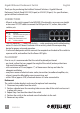
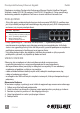
CONNECTIONS
• AllportsontheswitchsupportAuto-MDI/MDI-Xfunctionality,soyoucanusestraight
orcrossoverUTP/STPcablestoconnecttheRJ45portstoPCs,routers,hubs,other
switches, etc.
• TheLEDindicators—Power,Link/Activity—makemonitoringandtroubleshooting
easier.IfastatusLEDdoesn’tindicatealinkoractivity,checkthecorresponding
device for proper setup and operation.
• Usetheincludedpowercabletoconnectthereceptacleonthebackoftheswitchto
apoweroutlet,andconrmthatthePowerLEDlights.
PLACEMENT
Priortouse,itisrecommendedthattheswitchbeplaced/positioned:
• onalevelsurfacethatcansupporttheweightoftheswitch(andanyotheritems
that need to be considered);
• withaminimumof25mm(approx.1”)ofclearanceonthetopandsidesfor
adequate ventilation;
• awayfromsourcesofelectricalnoise:radios,transmitters,broadbandampliers,etc.;
• whereitcannotbeaectedbyexcessivemoisture;and
• within100m(approx.328’)ofnetworkdevicesit’stobeconnectedto.
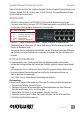
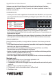
Rackmount
The switch includes brackets and screws for optional rack mounting.
1. Disconnectanycablesfromtheswitch.
2. Position a bracket over the mounting holes on one side of the switch and secure it
in place with screws.
3. RepeatStep2ontheothersideoftheswitch.
4. Position the switch in the rack and screw the brackets to the rack.
5. Reconnect any cables.
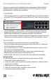
LED Status Operation
PWR On Power on
Off Check connection; turn power on
LNK/ On Valid port connection
ACT Blinking Data transmitted/received
Off No link established